
ENGINEERING DOCUMENTATION / REVIEW GUIDE
Laser sensor calibration and acceptance: define the result
Start with the quantity you need to accept, the conditions under which it is measured and the evidence that belongs to the delivered unit or complete system.
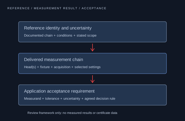
Read the specification terms as different questions.
| Term | What it can describe | What to ask alongside it |
|---|---|---|
| Resolution / output increment | Smallest reported step or stated detection capability under defined settings | Noise, bandwidth, averaging and actual measurement uncertainty |
| Repeatability | Variation under a defined repeated-measurement procedure | Statistic, sample count, target, time interval and environmental conditions |
| Linearity / deviation | Relationship to a reference over a defined span and fitting method | Reference points, residuals, span definition and uncertainty |
| Application acceptance | Agreement that the complete measurement meets a defined process requirement | Measurand, fixture, surfaces, dynamics, uncertainty and decision rule |
Identify the result, unit and report scope.
Request the exact device model, serial identity, firmware/settings, report revision and date. For a matched pair or measurement assembly, identify which heads, frame, controller and acquisition settings the report covers. A report on one head does not by itself qualify a thickness system.
Ask which reference artifact or instrument was used, the measuring points, approach directions, target finish, exposure/filtering and environmental conditions. State whether a supplied record is a factory check, a calibration report or an accredited calibration within a stated scope; do not treat those labels as interchangeable.
Read traceability together with uncertainty and purpose.
NIST describes metrological traceability as a property of a measurement result supported by a documented calibration chain. Its policy also explains why traceability alone does not establish that uncertainty is small enough for a particular use. A reference number or a logo is not the full evidence chain.
Ask for reported uncertainty, its basis and coverage information, and how reference, repeatability, environment and setup contributions were treated. Identify whether the result concerns one sensor distance, total thickness, a fitted profile or a registered surface map.
Do not convert a digital step, a repeatability figure or a reference-target result into a universal accuracy guarantee. Qualification on another surface, temperature, rate or filtering setup needs its own justification.
Agree the application test and decision rule before ordering.
Choose the actual measurand, datum, allowable deviation and reference comparison method. Define how uncertainty is treated near a tolerance boundary, who approves the result and what happens if the evidence is inconclusive. There is no universal pass rule for every customer process.
Include fixture/support variation, thermal stabilization, representative finishes, motion and invalid-data coverage. For thickness, include both heads, their alignment/synchronization and frame stability. For a profile or height map, retain evaluation regions and motion registration. For long-range positioning, include target return and complete data age.
Separate calibration from adjustment and from process acceptance. If a system is adjusted or its installation/settings change, agree what needs rechecking and retain the before/after records. Set the next review interval from use, stability history and quality requirements rather than assuming one interval suits every installation.
Special target trials, dedicated fixtures and third-party accredited calibration are separate scope questions. Confirm feasibility, responsibility, any additional cost and schedule in writing; this guide does not establish that such services are included or available.
PROPOSED REVIEW / NOT A COMPLETED TEST
Make the checks part of the agreed project scope.
Write the acceptance requirement
Define quantity, datum, conditions, tolerance and the reference method before choosing a headline sensor number.
Confirm available evidence
Request unit/system identity, report scope, reference chain, points, settings and uncertainty information.
Run representative conditions
Agree repeated, reload, range, finish, dynamic and invalid-data checks appropriate to the application.
Retain the decision and configuration
Record the accepted revision, uncertainty/decision rule, open limitations and conditions that trigger a recheck.
The proposed checks do not establish a released LDS model, completed calibration, accreditation or certified machine-safety function.
Questions before you request the files
Does a fine resolution mean the same absolute accuracy?
No. Output increment, noise, repeatability, linearity and measurement uncertainty describe different aspects. Compare the stated conditions and the complete measurement result required by your process.
Does traceability automatically make a result suitable for my process?
No. The documented reference chain and uncertainty must be reviewed against the intended measurement and acceptance requirement. Traceability alone does not establish fitness for purpose.
Is an LDS calibration certificate available to download here?
This page provides review guidance, not a certificate. Request the proposed configuration’s available calibration scope and report identity. No unit-specific or accredited report is established by a planning worksheet or an enquiry.
Request evidence for your actual configuration.
Send the full device and controller model, measuring requirement, document revisions already held, quantity and destination. Ask to agree an NDA and transfer method before sharing confidential drawings.
Download or read the project worksheet ↗HARDWARE / INSTALLATION REFERENCE
Identify the exact head and acquisition chain under test.
Record the unit identity and configuration alongside the reference, settings and environmental conditions.
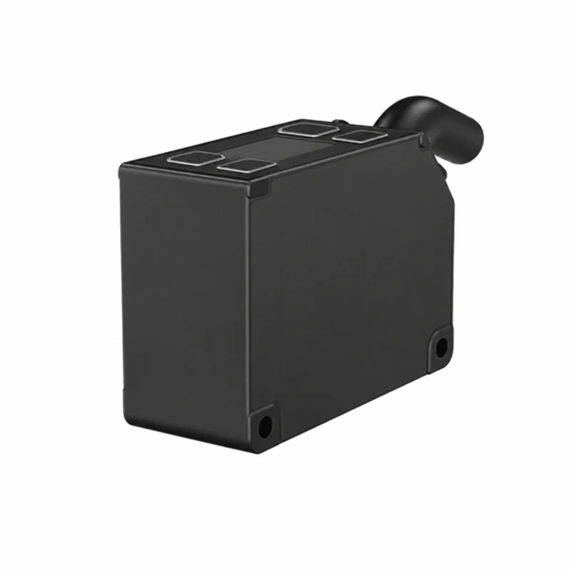
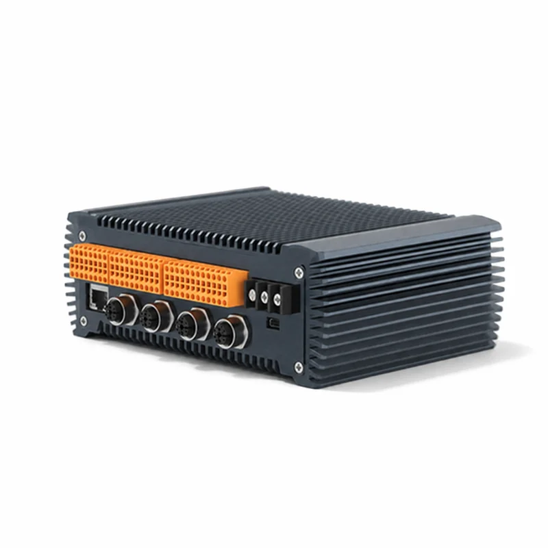
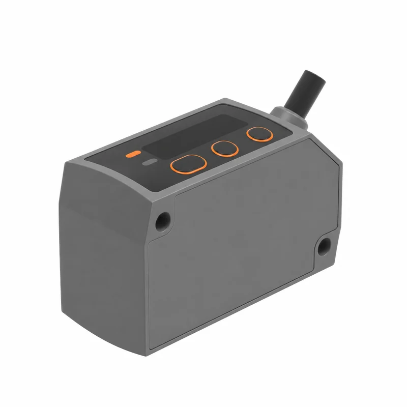
Representative housing views. Confirm the exact model, dimensions and supply scope. Housing color does not identify laser wavelength.