
LASER SENSORS BY TYPE
Industrial laser sensors.
Plan the sensor and its accessories.
Laser displacement, profile and distance measurement serve different jobs. Select a family, then define surface, accuracy and integration requirements.
Match point, profile or long-range geometry.
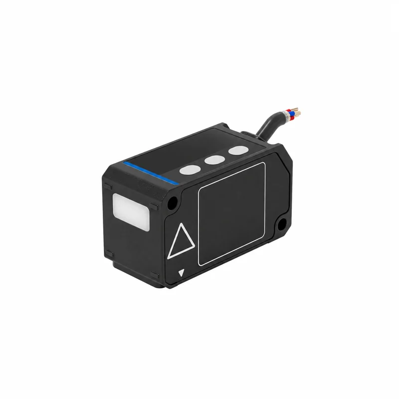
LDS-TRI
CMOS laser displacement sensors
25–1,000 mm distance requests
PCB warpage · robot positioning · packaging height
Explore configuration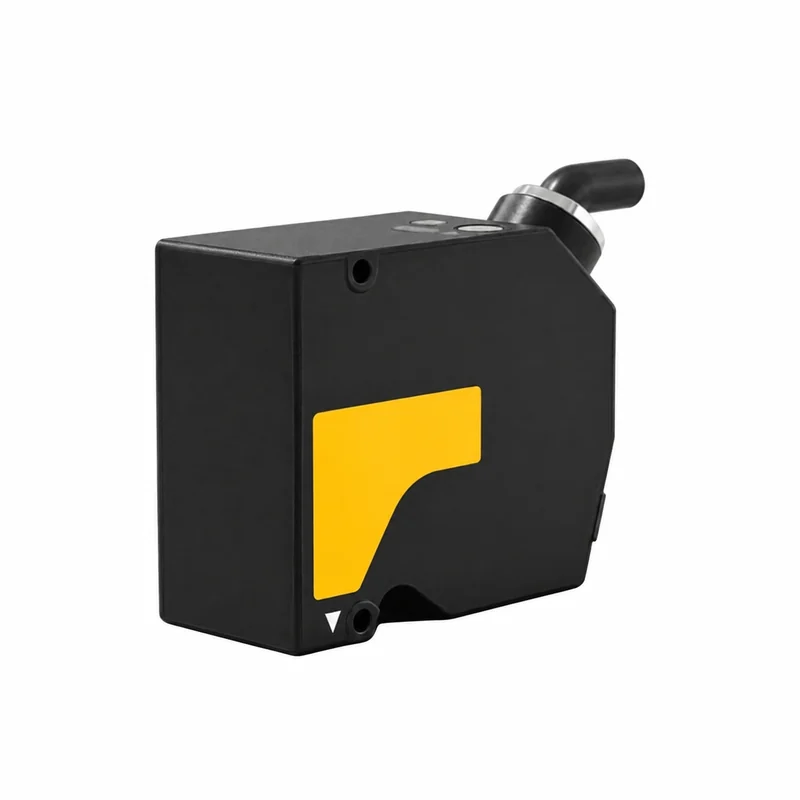
LDS-PRO
Sub-micron high-speed laser displacement gauges
10±2 to 150±40 mm requests
Electrode coating · wafer runout · spindle vibration
Explore configuration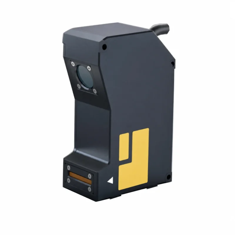
LDS-2D
2D laser profile sensors & line scanners
Z: 10–600 mm · X: 15–500 mm requests
Gap & flushness · weld cross-section · tire profile
Explore configuration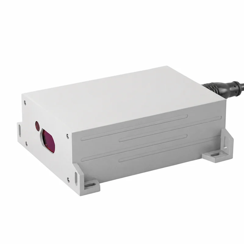
LDS-LNG
Long-range industrial laser distance sensors
0.05–50 m natural target · up to 150 m reflector requests
Stacker cranes · overhead cranes · industrial distance
Explore configuration| Measurement | Family | Primary selection decision | Explore |
|---|---|---|---|
| CMOS laser displacement sensors | LDS-TRI | 25–1,000 mm distance requests PCB warpage · robot positioning · packaging height | Review LDS-TRI ↗ |
| Sub-micron high-speed laser displacement gauges | LDS-PRO | 10±2 to 150±40 mm requests Electrode coating · wafer runout · spindle vibration | Review LDS-PRO ↗ |
| 2D laser profile sensors & line scanners | LDS-2D | Z: 10–600 mm · X: 15–500 mm requests Gap & flushness · weld cross-section · tire profile | Review LDS-2D ↗ |
| Long-range industrial laser distance sensors | LDS-LNG | 0.05–50 m natural target · up to 150 m reflector requests Stacker cranes · overhead cranes · industrial distance | Review LDS-LNG ↗ |
FOUR OPTION TYPES / CONFIGURATION REVIEW
Plan protection, cabling, optical variant and data processing.
Choose the function your installation needs, then confirm the exact hardware and document scope. These are enquiry options, not released accessory part numbers. Reference USD budgets are per option unit and do not establish availability, fit or an order total.
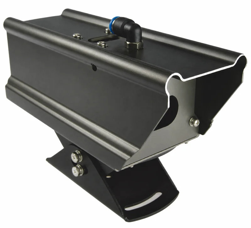
Air-purge dust shield / water-cooling protective housing
Separate lens cleanliness from sensor cooling.
Request a protective housing when dust, spray or radiant heat could disrupt the optical path. An air purge and a cooling circuit perform different jobs; neither establishes a higher sensor temperature rating by itself.
- Bring these installation details
- Head dimensions, emitting and receiving ray clearance, target stand-off, sensor ambient and radiant heat, dust/splash exposure, available clean air and coolant conditions.
- Request the actual evidence
- Housing/optical-clearance drawing, air and water connections, installation/maintenance instructions and environmental limits. Any added optical window needs a measurement review with the assembled sensor.
- Confirm the supply boundary
- Confirm which purge and cooling functions are included, housing quantity and fittings. One housing must not obstruct the outgoing beam or receiving cone; water leakage and condensation need installation review.
Planning reference: +USD 85 per requested option unit. Confirm quantities, scope and final quotation.
Request housing review ↗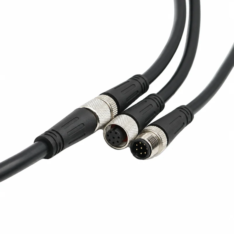
5m high-flex shielded M12 robot cable
Specify the connector and motion before cable length.
The 5m shielded M12 cable is an enquiry option. Matching connector size and pin count does not establish a matching pin assignment, signal path or drag-chain rating.
- Bring these installation details
- Full sensor/output variant, connector coding and gender, pin assignment, cable length, moving/fixed installation, bend radius, travel/speed, shielding/grounding and oil/coolant exposure.
- Request the actual evidence
- Both-end wiring drawing, cable construction, permitted fixed/dynamic bend conditions and flex-test scope. Review network impedance/transport requirements separately from analog or serial wiring.
- Confirm the supply boundary
- Agree each cable and connector quantity. A point-sensor cable is not automatically a profile-data cable, IO-Link lead or a fieldbus connection; no universal M12 replacement is implied.
Planning reference: +USD 48 per requested option unit. Confirm quantities, scope and final quotation.
Request cable review ↗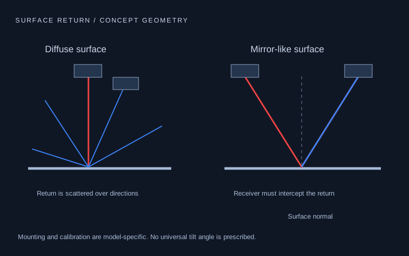
405nm violet-blue optical variant review
Review 405nm as an optical configuration.
A violet-blue optical variant can be considered for selected hot or difficult surfaces. The emitter, receiver geometry, filters and target response need a complete configuration review.
- Bring these installation details
- Actual surface/layer, temperature and background light, spot size, working distance, slope, exposure, usable rate and required measurement result.
- Request the actual evidence
- Exact optical variant identification, spot/clearance information, representative target-trial conditions and matching laser-safety documentation.
- Confirm the supply boundary
- This is not a field emitter swap or a promise that transparent, black or mirror targets will measure correctly. Long-range phase-shift requests do not inherit this option; confocal and micrometer work needs its own scope.
Planning reference: +USD 140 per requested option unit. Confirm quantities, scope and final quotation.
Request blue-optics review ↗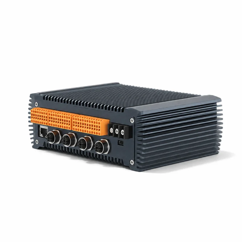
Dual-channel display & tolerance comparator
Distinguish a comparator from paired acquisition.
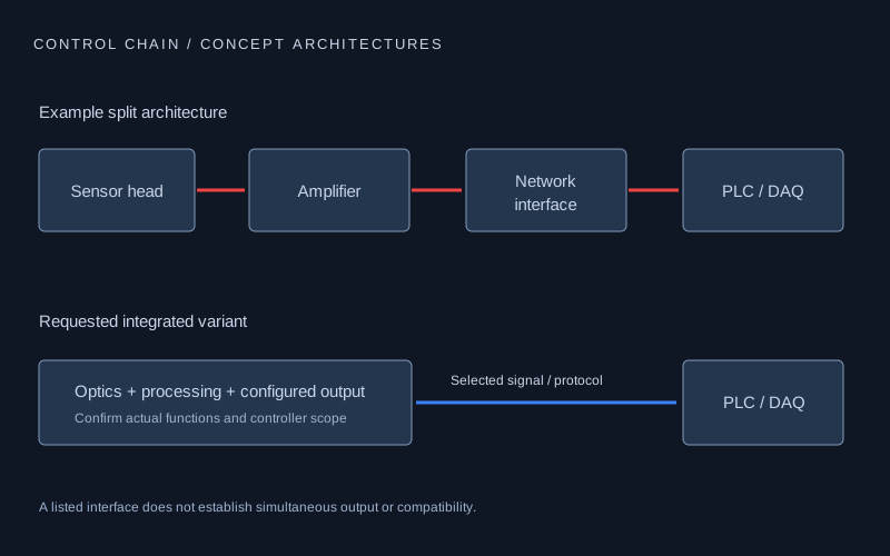
A dual-channel display can present readings and tolerance results, but its channel count alone does not establish simultaneous sampling or a high-speed thickness calculation.
- Bring these installation details
- Input types/scaling, update and filter behavior, trigger/timestamp pairing, invalid/stale value handling, comparison outputs, PLC path and required cycle time.
- Request the actual evidence
- Controller input/output and wiring specification, timing/data-flow description and agreed acceptance method. For thickness, review matched heads and frame geometry as part of the system.
- Confirm the supply boundary
- Agree controller/module quantity independently of head and station counts. A display budget does not include a qualified synchronizer, network gateway, frame or calibrated thickness system.
Planning reference: +USD 185 per requested option unit. Confirm quantities, scope and final quotation.
Request display review ↗Use the measurement family to set the review boundary.
- LDS-TRI / LDS-PRO: review the ordered optical/output variant, working distance and each installation item; a family name does not confirm accessory fit.
- LDS-2D: preserve the complete emitting line/receiving field and profile-data path; a point-sensor cover or lead is not automatically suitable.
- LDS-LNG: review thermal protection, alignment, target return and cable/protocol separately. The 405nm point-sensor optical option is excluded.
- Confocal / optical micrometer / unresolved method: define a separate system scope before using ordinary laser accessory budgets.
Resolve scope before ordering installation options.
Does selecting an accessory confirm it fits my sensor?
No. It adds a review request. The written configuration must identify the sensor and optical/output variant, accessory drawing, interface, quantities and operating conditions before suitability can be confirmed.
Does one protection budget include air purge and water cooling?
Do not assume both are included. Specify the required functions, connections, utilities and quantity. The reference amount is a planning allowance for an option unit; the delivered scope and price require a written quotation.
Why was a requested option not selected in the enquiry?
The enquiry excludes blue optics for long-range requests and ordinary laser options for separate advanced-method reviews. It names excluded requests visibly; review the measurement method or describe a separate requirement in the project notes.
Can I use the display budget as a complete thickness controller price?
No. Paired acquisition, timing, invalid data, frame reference and system acceptance need a separate scope. Use the opposed-head system planner for stations and supply responsibilities; it does not infer a qualified controller or final price.
Engineering background: optoNCDT 2300 manual: protective housing and cable installation; Blue Laser optical arrangements; thicknessSENSOR system architecture. These describe manufacturer-specific designs; their ratings do not establish LDS accessory performance.
Compare the complete installation cost.
Compare two USD acquisition scopes, identify missing costs and take the worksheet to the engineering enquiry.
Open the price and scope worksheet ↗FROM COMPONENT TO MEASUREMENT
Work from the process to the sensor.
Battery electrode & sheet thickness
Specify the complete measurement loop: two surfaces, two synchronized distance readings and one calibrated frame. Start by defining whether you need total sheet thickness or coating thickness alone.
Review the measurement plan ↗SEMICONDUCTOR / PCB / PRECISION ASSEMBLYWafer & PCB warpage
A height map becomes useful only when its reference plane, support condition and scan coordinates are defined. Treat an opaque PCB, a polished wafer and a transparent layer stack as separate optical jobs.
Review the measurement plan ↗BODY PANELS / DOOR FIT / ROBOT INSPECTIONAutomotive gap & flushness
Turn a door, hood or body-panel cross-section into two defined results: lateral separation and signed height offset. The profile, reference regions and edge rule must describe the same inspection task.
Review the measurement plan ↗ASRS / MATERIAL HANDLING / PLANT TRAVELCrane & stacker positioning
Specify a distance channel over the complete travel path, including the nearest position, moving target alignment and control-system timing. A long maximum range alone does not establish a usable positioning loop.
Review the measurement plan ↗ADDITIONAL OPTICAL METHODS / TECHNOLOGY REVIEW
Measuring interfaces or an outside diameter?
Confocal Chromatic Sensor Review
Assess single-sided surface or transparent-layer measurement using a broadband optical principle. Identify the return you need, then qualify the head, controller and material calibration together.
Review the method and access requirements ↗Laser Micrometer Diameter Review
Measure a projected diameter, width or edge with transmitted light. Define emitter/receiver access and the target envelope before selecting an optical aperture or reporting a dimensional result.
Review the method and access requirements ↗Prepare the drawings, data and acceptance scope.
Laser Sensor PLC Integration Guide
Confirm the ordered hardware, wiring drawing and data semantics together. An M12 connector or an Ethernet port describes only part of the integration.
Open the engineering checklist ↗Laser Sensor Calibration Review
Start with the quantity you need to accept, the conditions under which it is measured and the evidence that belongs to the delivered unit or complete system.
Open the engineering checklist ↗Laser Sensor Safety & Compliance
Prepare one review package for the ordered head, its optical variant and the machine around it. Start with identifiable documents and the access conditions your EHS team needs to assess.
Open the engineering checklist ↗Complete the sensing chain.
Review matched heads, dual-channel synchronization, C-frame brackets, air-purge housings, cooling, cables and displays with your sensor selection.
Ask for a complete configuration ↗