
BODY PANELS / DOOR FIT / ROBOT INSPECTION
Automotive gap and flushness measurement from one profile
Turn a door, hood or body-panel cross-section into two defined results: lateral separation and signed height offset. The profile, reference regions and edge rule must describe the same inspection task.
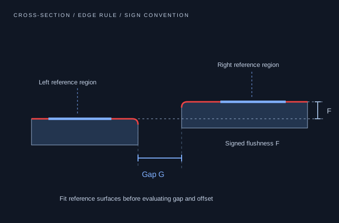
Agree the gap edges and flushness reference first.
Rounded edges, chamfers and curved panels can give several plausible numbers from the same profile. A repeatable result needs an explicit evaluation rule.
| Decision | Define in the inspection plan | Why it changes the result |
|---|---|---|
| Gap width | Observed edge points or intersections of fitted reference geometry | A rolled edge and a sharp edge do not produce the same threshold location |
| Flushness | Which side is the datum, evaluation position and positive direction | Height offset depends on reference regions and local surface slope |
| Profile plane | Scanner pose and cross-section direction relative to the seam | An oblique section can inflate apparent gap width |
| Quality flags | Required valid points, fit residual and missing-edge behavior | A numerical value without valid edges can become a false pass |
BEFORE THE PURCHASE ORDER
Use signed reference parts to verify both values and validity.
Agree the reference method
Choose traceable reference parts or a suitable comparison method for the actual curved or rolled edges. Record the evaluation positions and sign convention.
Test the production envelope
Cover minimum/maximum gap, both flushness signs, panel tilt and pose changes. Include each relevant finish and deliberate missing-edge cases.
Inspect dynamic profiles
Run at planned robot speed and acceleration. Compare registered profiles with stationary checks and verify exposure, trigger and motion synchronization.
Exercise the reject path
Verify invalid flags, stale data and missing profiles in the PLC. Archive enough raw profiles to explain a failed inspection and define operator recovery.
These are proposed validation steps. They do not represent completed testing, a calibration certificate or a performance commitment for an LDS configuration.
Fit the useful panel regions, then evaluate the edges.
Place the laser line so both panel surfaces and the gap edges remain visible throughout the allowed assembly variation. Include receiving-optics clearance, robot pose error and maximum panel height difference when sizing the X/Z field.
Check the emitter-to-receiver viewing plane relative to the seam as well as the projected line direction. A deep gap or high-side edge can hide the opposite edge from the receiver even when the laser line crosses both panels. Review the scanner’s actual optical drawing and trial the proposed mounting pose.
Define regions on the two panel surfaces away from the edge roll-off. Fit the agreed line or curve in each region, locate the gap by the chosen edge rule and calculate flushness at the specified reference position. Keep the raw profile with the result during commissioning so the rule can be reviewed.
Challenge paint, sealant and occluded edges.
Bare metal, metallic paint, dark paint and mixed finishes may require different exposure behavior. A deep gap can shadow the receiving path. Sealant or a protective film can add a feature that the algorithm mistakenly treats as the panel edge.
Include these variants in the target trial and define when the system must return invalid rather than interpolate a missing edge. Optical shielding and purge arrangements can reduce contamination exposure, but their suitability depends on the installation and maintenance plan.
Budget robot motion and PLC data independently.
At constant traverse speed v, nominal along-seam spacing is v divided by effective profile rate f. An illustrative 0.5 m/s traverse at 1,000 profiles/s gives 0.5 mm spacing. This does not establish feature accuracy, exposure blur, encoder registration or the LDS scanner rate available on your surface.
Choose whether the PLC receives processed gap/flushness results or a separate industrial PC processes raw profiles. Specify protocol, result units, sequence number, timestamp and quality flags. A standard Ethernet socket is not a declaration of GigE Vision or a particular fieldbus implementation.
HARDWARE / INSTALLATION REFERENCE
Leave clearance around the complete profile-scanning head.
Compare head geometry, connector direction and receiving aperture with the robot approach and panel access.
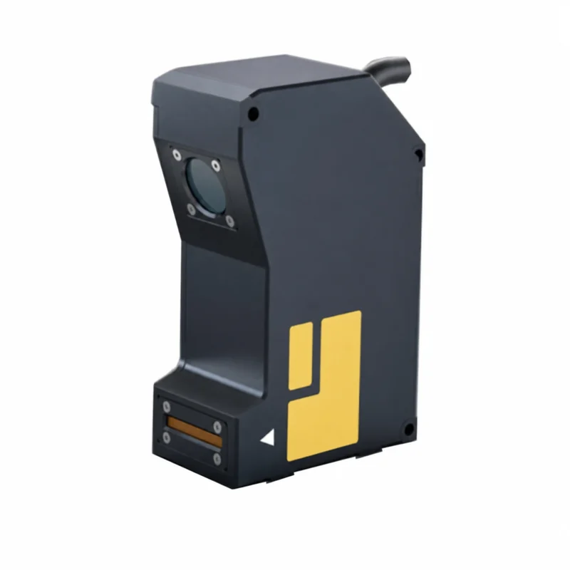
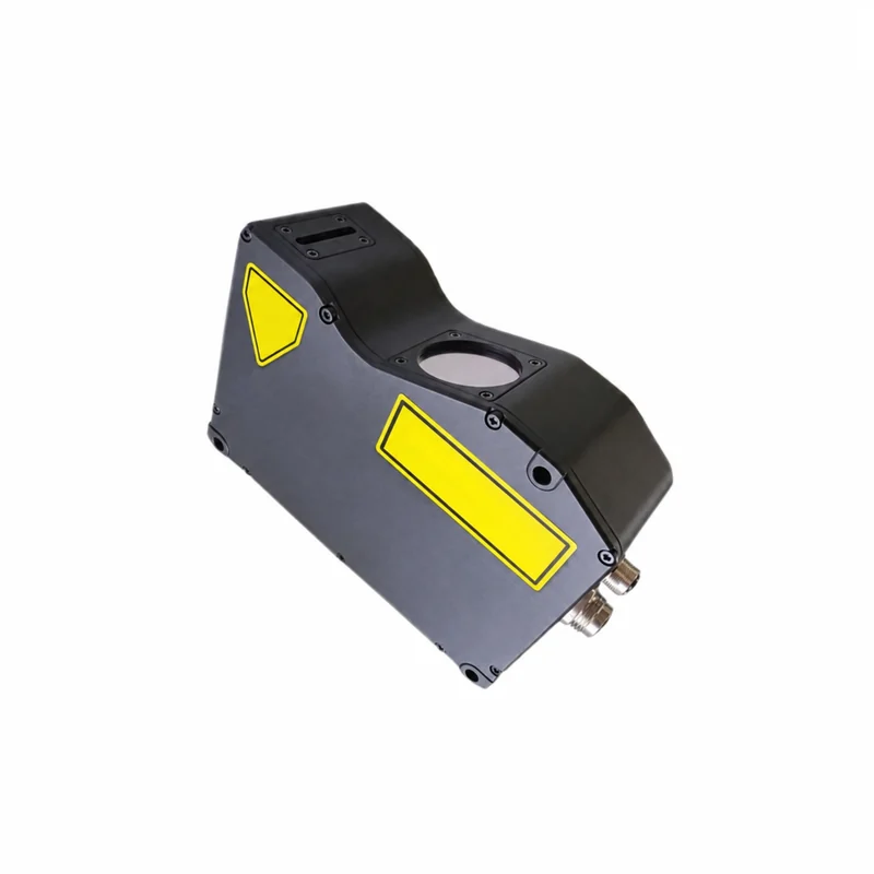
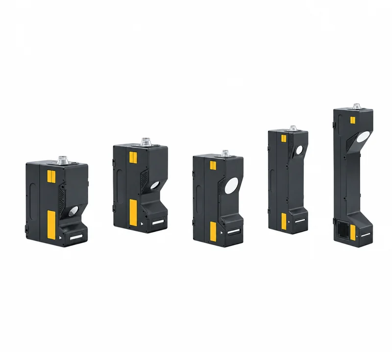
Representative housing views. Confirm the exact model, dimensions and supply scope. Housing color does not identify laser wavelength.
Compare the sensing options for this task.
2D laser profile sensors & line scanners
Z: 10–600 mm · X: 15–500 mm requests
Review configuration and integration ↗Request LDS-2D for this application ↗Questions before you specify the system
Can a 2D laser scanner measure gap and flushness together?
A suitable profile can contain both panel surfaces and their edges. Software must apply defined edge and reference rules, then return both results with validity flags. The required field, optical access and finish still need qualification.
Is the maximum profile point count the gap accuracy?
No. Point count describes sampling across a field. Accuracy also depends on field size, optics, calibration, surface return, edge geometry, fitting and installation.
Can every raw profile be sent directly to the PLC?
Not necessarily. Confirm the controller payload and cycle budget. Many integrations send processed scalar results to the PLC while raw profiles go to an industrial PC or recorder through a separately specified interface.
Automotive gap & flushness / ENGINEERING HANDOFF
Send the process conditions with the request.
Gap limits; signed flushness definition; panel curvature and edge radii; paint or bare-metal finish; working envelope; robot speed; profile spacing; PLC and result format.
Include your existing sensor/controller model, required document revisions, quantity and destination. After reviewing the brief, the next step is a proposed configuration and confirmation of the available drawings, integration information and test scope before a formal quotation.
The form retains this application-page context. Confirm the actual family and range for your machine. For confidential drawings, agree an NDA and transfer method before sending files.
Prepare the drawings, data and acceptance scope.
Laser Sensor PLC Integration Guide
Confirm the ordered hardware, wiring drawing and data semantics together. An M12 connector or an Ethernet port describes only part of the integration.
Open the engineering checklist ↗Laser Sensor Calibration Review
Start with the quantity you need to accept, the conditions under which it is measured and the evidence that belongs to the delivered unit or complete system.
Open the engineering checklist ↗Laser Sensor Safety & Compliance
Prepare one review package for the ordered head, its optical variant and the machine around it. Start with identifiable documents and the access conditions your EHS team needs to assess.
Open the engineering checklist ↗