
BATTERY ELECTRODES / STRIP / SHEET
Dual-head laser thickness measurement for moving sheets
Specify the complete measurement loop: two surfaces, two synchronized distance readings and one calibrated frame. Start by defining whether you need total sheet thickness or coating thickness alone.
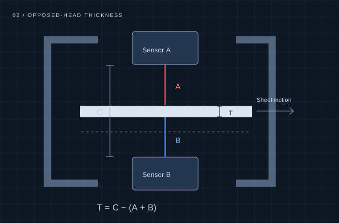
ONE PAIR PER STATION / SUPPLY RESPONSIBILITIES
Count the stations, then define who supplies each part.
Plan total outer-surface thickness with one dedicated opposed pair per station. This does not select a coating-only method or establish hardware suitability. A station count is different from the free-text purchase quantity in the enquiry. Shared heads or another station arrangement need a separate review.
1 measuring station · 2 planned point channels
Requested new sensor heads: To confirm
- Matched sensor heads
- Responsibility to confirm
- Synchronization & acquisition
- Responsibility to confirm
- Frame & reference geometry
- Responsibility to confirm
- System acceptance work
- Responsibility to confirm
Mixed or unresolved supply: no complete core kit quotation selected.
One opposed pair per station. These are planning roles, not controller, frame or cable quantities. Reconcile the separate purchase quantity, accessories and budget in the written quote. Compatibility, uncertainty, documents and price remain to be confirmed.
Attaching/sharing a link includes the station count and selected responsibilities in its URL; the enquiry sends them by email. Keep confidential project data out of shared links. The local text download needs no contact details. Editing imported values clears the old URL snapshot. No order, price or calibration certificate is created.
Separate total thickness from coating-only measurement.
An opposed optical pair sees the two outer surfaces. The result includes the substrate and every coating between them; it does not identify individual layers by itself.
| Measurement objective | Starting arrangement | Information needed |
|---|---|---|
| Total opaque sheet thickness | Opposed, aligned point sensors with synchronized acquisition | Thickness extremes, both surface finishes, flutter and frame opening |
| Coating added to a known substrate | Compare total thickness with independently established substrate thickness | Substrate variability and the uncertainty of both measurements |
| Separate top and bottom coating layers | Additional layer-sensitive or process-reference measurement | Opaque layers cannot be separated by this laser pair alone; review process references or separately scoped sensing |
| Transparent film or multilayer stack | Optical technology review before specifying a triangulation pair | Refractive index, layer separation, transparency and required result |
Close the geometry before choosing a resolution.
T = C − (A + B)
T is total thickness. C is the calibrated separation between the two distance reference planes. A and B are positive distances measured from each head toward its facing surface along a common axis. Relative or sign-inverted outputs must first be transformed to these coordinates. Mounting dimensions alone do not establish C.
In the ideal aligned arrangement, rigid sheet translation increases one distance and decreases the other by the same amount. Actual performance also depends on frame expansion, sheet tilt, lateral spot mismatch, sensor linearity and optical response. A digital output increment is not the uncertainty of the thickness result.
For parallel faces tilted by θ to the perpendicular of the measurement axis, the intercepted thickness is Tₙ / cos θ, where Tₙ is thickness normal to the sheet. Even aligned spots need an agreed tilt limit. Triangulation cannot see through opaque electrode coatings; separating individual layers needs process-reference measurements or another sensing method, with supply scope confirmed separately.
Match acquisition timing to web motion.
Ask how each head is triggered and how readings are paired. A PLC polling two values in sequence does not establish simultaneous acquisition. Record timestamps, invalid-value handling, averaging windows and the behavior when one head loses the surface.
For locally constant normal sheet velocity, timing mismatch produces an approximate error magnitude |vₙ × Δt|. An illustrative 0.1 m/s normal motion and 100 μs mismatch correspond to 10 μm. This is geometry arithmetic, not a measured LDS result; web travel speed along the sheet is a different quantity.
Choose a usable rate after exposure and filtering are fixed. For a moving web, along-track sample spacing is line speed divided by effective paired sample rate. A single track is not a full-width thickness map: traversing or multiple tracks require a separate position and synchronization plan.
Qualify the frame, surfaces and delivered data together.
Begin with LDS-PRO for demanding dynamic measurements and review LDS-TRI where the required tolerance and speed permit. Neither family name qualifies the complete gauge. Keep the expected sheet excursion inside both heads’ usable ranges, including thickness extremes and mounting tolerances.
Electrode texture, wet coatings and metallic substrate exposure can produce different return signals. Request a trial on representative material at the intended line speed. Agree how dropouts, coating edges, seams and transitions are flagged instead of silently substituted by held values.
BEFORE THE PURCHASE ORDER
Agree a thickness acceptance test before the pair is ordered.
Establish the reference
Record master thickness values and their uncertainty, calibration method, frame temperature and reference separation. Include more than one thickness across the intended span.
Challenge translation and tilt
Move the same master through the permitted position and angle envelope. Log both raw distances, calculated thickness and invalid flags; repeat after warm-up.
Run representative material
Test actual surface variants at the planned speed, exposure and averaging. Define acceptable deviation, valid-reading coverage and restart behavior in advance.
Verify the complete PLC path
Check paired timestamps, units, scaling, update interval and stale-data response. Include the frame, cables and controller in the written supply scope.
These are proposed validation steps. They do not represent completed testing, a calibration certificate or a performance commitment for an LDS configuration.
HARDWARE / INSTALLATION REFERENCE
Scope the heads, acquisition and complete station separately.
An opposed-head measurement needs a matched optical arrangement and synchronized data. An enclosure or controller alone does not establish that capability.
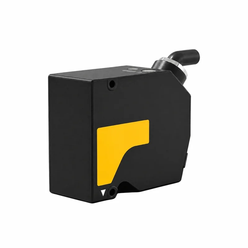
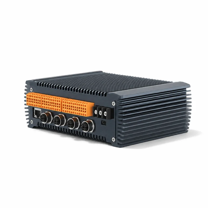
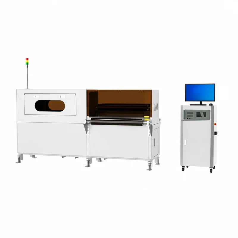
Representative housing views. Confirm the exact model, dimensions and supply scope. Housing color does not identify laser wavelength.
Compare the sensing options for this task.
Sub-micron high-speed laser displacement gauges
10±2 to 150±40 mm requests
Review configuration and integration ↗Request LDS-PRO for this application ↗CMOS laser displacement sensors
25–1,000 mm distance requests
Review configuration and integration ↗Request LDS-TRI for this application ↗Questions before you specify the system
Can two laser sensors measure coating thickness alone?
An opposed pair measures total outer-surface thickness. Coating-only thickness requires a known substrate thickness or an additional measurement that distinguishes the relevant interfaces. Include substrate variation in the uncertainty budget.
Does a dual-head pair cancel all sheet vibration?
Ideal aligned and simultaneous readings cancel rigid translation along the measurement axis. Timing mismatch, tilt, lateral spot separation, frame motion and surface-dependent errors remain and must be tested.
Is a fixed micron accuracy guaranteed for the kit?
No universal kit accuracy is assigned. Specify the material, span, speed, thermal conditions and acceptance method so the complete sensor, frame and acquisition assembly can be qualified.
Battery electrode & sheet thickness / ENGINEERING HANDOFF
Send the process conditions with the request.
Total thickness or coating-only result; substrate and coating stack; min/max thickness; web speed; flutter; C-frame gap; required uncertainty; trigger and PLC cycle.
Include your existing sensor/controller model, required document revisions, quantity and destination. After reviewing the brief, the next step is a proposed configuration and confirmation of the available drawings, integration information and test scope before a formal quotation.
The form retains this application-page context. Confirm the actual family and range for your machine. For confidential drawings, agree an NDA and transfer method before sending files.
Prepare the drawings, data and acceptance scope.
Laser Sensor PLC Integration Guide
Confirm the ordered hardware, wiring drawing and data semantics together. An M12 connector or an Ethernet port describes only part of the integration.
Open the engineering checklist ↗Laser Sensor Calibration Review
Start with the quantity you need to accept, the conditions under which it is measured and the evidence that belongs to the delivered unit or complete system.
Open the engineering checklist ↗Laser Sensor Safety & Compliance
Prepare one review package for the ordered head, its optical variant and the machine around it. Start with identifiable documents and the access conditions your EHS team needs to assess.
Open the engineering checklist ↗