
ASRS / MATERIAL HANDLING / PLANT TRAVEL
Laser positioning for cranes and warehouse stackers
Specify a distance channel over the complete travel path, including the nearest position, moving target alignment and control-system timing. A long maximum range alone does not establish a usable positioning loop.
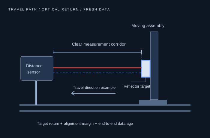
Keep a clear optical corridor as the structure moves.
A fixed sensor can view a target on the travelling assembly, or the arrangement can be reversed if cable routing and alignment allow. Define the mounting reference and distance direction. Account for loaded structure deflection, rail variation and target tilt at every travel position.
Check the actual beam footprint from the proposed model’s drawing and the full expected alignment excursion. Keep the footprint and its motion margin inside the target. Do not use a model-independent spot-size number to size a distant reflector.
Dust, steam, radiant heat and direct sunlight can affect return signal or create intermittent invalid readings. A hot workpiece does not define the sensor ambient temperature. Specify shielding, purge air quality, cooling limits and an inspection interval with the enclosure.
Turn update specifications into a control timing budget.
Separate acquisition time, averaging, internal processing, network transfer and PLC scan. Ask whether the reported update rate means a new independent reading or a repeated held value. A fine display increment is not a statement of absolute distance accuracy.
For constant speed, uncorrected data age produces a position lag magnitude v × τ. As an illustrative budget, 2 m/s and 20 ms total age correspond to 40 mm. This is a timing calculation, not sensor error or a stopping-distance calculation; acceleration and controller compensation require separate assessment.
Map diagnostics before commissioning the motion loop.
Define scaling, origin, positive direction and behavior outside the measuring range. For analog integration, specify the valid current/voltage range and the ordered model’s fault behavior. For digital integration, include validity status, sequence or timestamps, and timeout handling.
LDS-LNG requests are reviewed by target, travel range and interface variant. A matching Dimetix, SICK or Banner range is only a starting comparison: connector wiring, communication semantics, timing and mechanical alignment must also be checked. Process distance measurement does not establish a certified collision-prevention or personnel-protection function.
Size the target and timing across minimum and maximum travel.
Review natural-target and reflector operation separately. A reflective target can improve return while introducing its own minimum-distance and saturation conditions.
| Installation choice | What to specify | What to verify |
|---|---|---|
| Natural surface | Material, color, target size and angle along the entire path | Valid return at the far limit and under the worst ambient light |
| Reflector target | Approved reflector type, size, mounting and near limit | Model-specific minimum distance, alignment margin and saturation behavior |
| Moving machine | Maximum speed, vibration, deflection and target displacement | Beam remains on target; update timing and stale-data behavior meet the control plan |
| PLC interface | Analog or exact digital protocol, cycle and status mapping | End-to-end latency, units, direction and diagnostic handling |
BEFORE THE PURCHASE ORDER
Test the full travel path, including lost return.
Survey the static path
Compare known positions at the near, middle and far limits. Record target, temperature, light and alignment. Confirm both approach directions and the configured zero.
Run loaded movement
Repeat at planned speed with representative machine loading. Log distance, quality flags, timestamps and PLC receipt time to assess the complete timing budget.
Challenge the optical return
Exercise expected target angles, sunlight and contamination conditions under an agreed test procedure. Check recovery after a temporary blocked beam.
Verify the control response
Agree the machine response to invalid or stale data with the control-system owner. Validate it separately from any safety-rated system and document reset behavior.
These are proposed validation steps. They do not represent completed testing, a calibration certificate or a performance commitment for an LDS configuration.
HARDWARE / INSTALLATION REFERENCE
Review alignment, mounting and protection along the travel path.
The sensor, mounting bracket and protective enclosure need a common optical-clearance review.
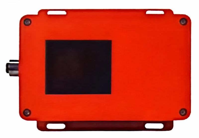
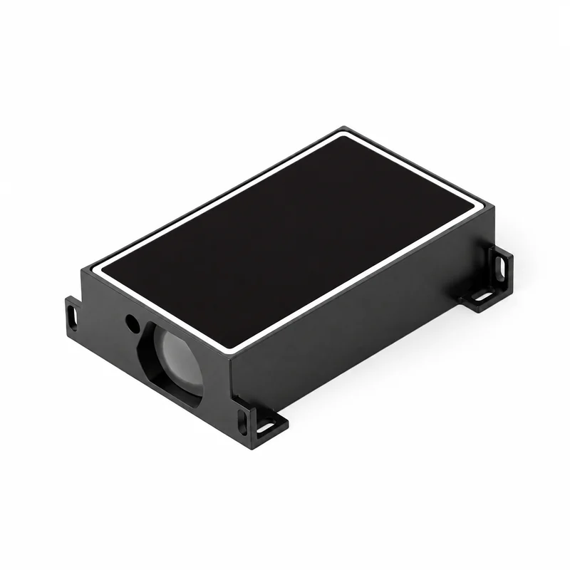
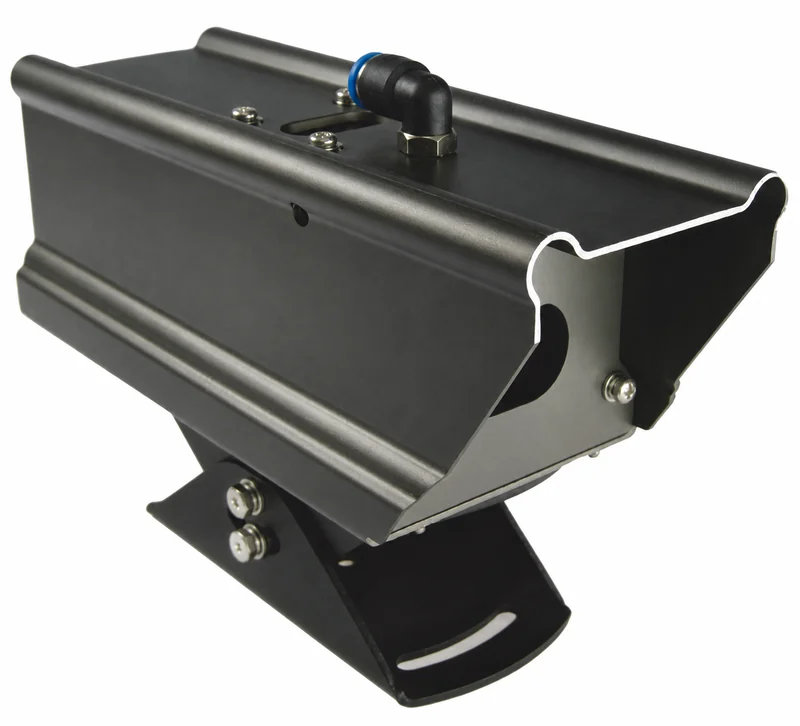
Representative housing views. Confirm the exact model, dimensions and supply scope. Housing color does not identify laser wavelength.
Compare the sensing options for this task.
Long-range industrial laser distance sensors
0.05–50 m natural target · up to 150 m reflector requests
Review configuration and integration ↗Request LDS-LNG for this application ↗Questions before you specify the system
Does a 150 m range request apply to every surface?
No. Range depends on the ordered model, reflectivity, target size, ambient light and measuring settings. Natural-target and reflector limits must be confirmed separately, including the minimum distance.
Is a fast network cycle the same as a fresh distance reading?
No. Acquisition, averaging, processing and transfer all contribute to data age. Confirm the rate of new independent measurements and how invalid or held values are identified.
Can this distance channel be used as a certified anti-collision system?
No safety certification is established by this application guide. A process measurement channel must be assessed separately from the machine’s required safety functions by the responsible system designer.
Crane & stacker positioning / ENGINEERING HANDOFF
Send the process conditions with the request.
Minimum/maximum travel distance; target or reflector dimensions; speed; required update time; alignment and vibration; dust, sunlight and temperatures; PLC interface and loss-of-signal response.
Include your existing sensor/controller model, required document revisions, quantity and destination. After reviewing the brief, the next step is a proposed configuration and confirmation of the available drawings, integration information and test scope before a formal quotation.
The form retains this application-page context. Confirm the actual family and range for your machine. For confidential drawings, agree an NDA and transfer method before sending files.
Prepare the drawings, data and acceptance scope.
Laser Sensor PLC Integration Guide
Confirm the ordered hardware, wiring drawing and data semantics together. An M12 connector or an Ethernet port describes only part of the integration.
Open the engineering checklist ↗Laser Sensor Calibration Review
Start with the quantity you need to accept, the conditions under which it is measured and the evidence that belongs to the delivered unit or complete system.
Open the engineering checklist ↗Laser Sensor Safety & Compliance
Prepare one review package for the ordered head, its optical variant and the machine around it. Start with identifiable documents and the access conditions your EHS team needs to assess.
Open the engineering checklist ↗