
GEOMETRY / SIGNAL / MEASUREMENT DEFINITIONS
How does a laser displacement sensor work?
A laser displacement sensor turns an optical observation into a distance or position result. Triangulation uses the position of a reflected image; phase and pulsed distance methods use light-propagation information. The right question is which result your target, access and timing allow.
Engineering guide by LDS Optical Metrology · Published and reviewed . Concepts and illustrative arithmetic do not establish LDS model performance.
HARDWARE / INSTALLATION REFERENCE
Connect the optical concept to the installation envelope.
Point, profile and distance housings expose different apertures and mounting arrangements. The internal method must be confirmed from model documentation.
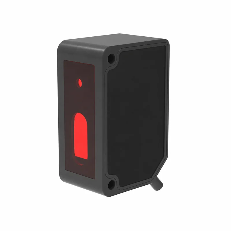
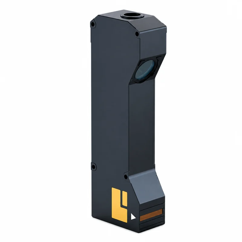
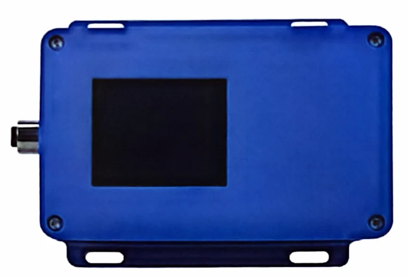
Representative housing views. Confirm the exact model, dimensions and supply scope. Housing color does not identify laser wavelength.
From reflected image position to a calibrated distance
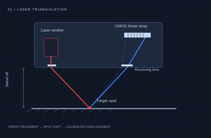
- The emitter illuminates a small region of the target.
- An offset receiver images returned light onto a position detector, such as a CMOS array.
- The electronics estimate the image position and convert it through the calibrated optical relationship.
- The configured signal path provides a reading and, where supported, validity/status information to the controller.
A detector pixel is not a fixed universal distance increment at the target. Lens geometry, calibrated range, signal estimation and noise all affect the resulting measurement. Diffuse and specular arrangements collect different parts of the return; a shiny tilted surface may direct light away from a receiver that works on a matte target.
Background: reflected-image arrangements and triangulation families.
Choose the observed quantity before the distance band.
| Method | Observed information | First application check |
|---|---|---|
| Point triangulation | Position of a returned spot/image | Surface return, receiving angle, near/far envelope and feature size. |
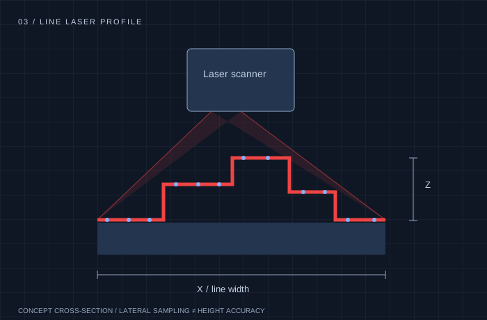
| Laser line profiling | A cross-section reconstructed across an illuminated line | Complete X/Z field, lateral sampling, shadows and motion reference. |
| Phase-based distance | Delay of a modulated return signal | Target return, ambiguity handling, environmental conditions and update behavior. |
| Direct pulsed time-of-flight | Round-trip pulse timing | Instrument-specific range, timing method and return-signal envelope. |
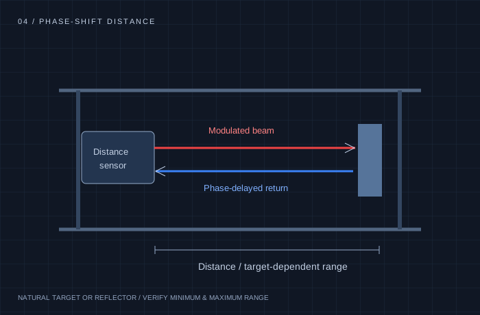
Phase-shift ranging evaluates modulation delay. Phase wrapping must be resolved by the instrument, for example with additional modulation information. Direct pulsed time-of-flight evaluates travel timing instead. Neither automatically inherits the uncertainty of a short-range triangulation measurement. The visible emitter wavelength alone does not tell you the unambiguous range of a modulation-based instrument.
Spectral confocal measurement uses wavelength-dependent focus and a shared optical path; transparent-layer work also needs suitable interfaces and material interpretation. A through-beam micrometer measures an edge or silhouette and needs emitter/receiver access. Specify the measurand and optical access before treating either as a distance-sensor replacement.
Compare all six optical assessment routes ↗Method background: Hamamatsu geometrical and propagation methods.
Resolution, repeatability and uncertainty answer different questions.
| Term | Meaning to check | Request these conditions |
|---|---|---|
| Near/far distance and span | Positions use a defined sensor datum. Span is far minus near, not the stand-off itself. | Exact distance origin, near/far limits and optical clearance. |
| Resolution / output increment | Distinguish a detectable change from a reported increment and its stated conditions. | Target, measuring rate, exposure, filtering and how the figure is specified. |
| Repeatability | Spread of repeated results under defined repeat conditions. | Statistic or limits, number of readings, fixtures, motion and averaging. |
| Linearity | Departure from the stated reference relationship over a specified interval. | Span, reference fit, units or percentage basis and test conditions. |
| Accuracy / uncertainty | Closeness to a reference and a quantified uncertainty evaluation are different descriptions. | Reference measurements, uncertainty components, conditions and acceptance rule. |
| Fresh-reading rate / latency | New measurement production and result delay are different from interface polling. | Exposure/filter windows, trigger/timestamps, packet timing and stale/invalid handling. |
A small display step does not establish closeness to a reference. A complete uncertainty evaluation may include sensor behavior, reference measurements, mounting, temperature and the target. Keep stated specification conditions attached to every comparison rather than ranking devices by their smallest advertised number.
Build the calibration and acceptance review ↗Definition and reporting background: NIST uncertainty guidance.
ILLUSTRATIVE CONFIGURATION / VALID LINEAR READINGS ONLY
Translate a defined measuring interval into a signal.
Suppose a requested geometry has a center distance of 100 mm and half-span 40 mm. Its near limit is 60 mm, far limit 140 mm and total span 80 mm. The sensor datum and usable interval still require actual model documentation.
For this example only, configure a positive linear current mapping: 4 mA at 60 mm and 20 mA at 140 mm. If I is a valid reading expressed in mA:
D = 60 mm + ((I − 4) / 16) × 80 mm
- 4mA
- 60mm near endpoint
- 12mA
- 100mm midpoint
- 20mA
- 140mm far endpoint
This is interpolation, not calibration or an uncertainty result. A reversed mapping, zero-relative output, different taught window or nonlinear configuration requires its own conversion. Do not interpret out-of-range, lost-signal or held values as valid positions; confirm the exact variant, polarity, status and analog input scaling.
Request the configured wiring and signal map ↗Why mapping must be checked: Banner's configurable output-window example. No Banner setting or fault value is an LDS default.
Test the surface, motion and complete data path together.
- Return signal: compare dark, bright, specular and layered regions on the actual target. Exposure control and a blue optical variant do not guarantee a valid return.
- Optical clearance: allow for both the emitted beam and receiver field over the full near/far travel. A bracket, edge or protective window can change the usable arrangement.
- Time: define exposure, filtering, fresh-reading rate and latency. Faster polling does not make held or repeated values new measurements.
- System result: opposing thickness heads need aligned, paired acquisition and an established frame gap; a line profile needs the intended feature/position definition.
Resolve the principle before specifying a model.
Can two sensors measure thickness?
An opposed pair can measure total outer-surface thickness using T = C − (A + B), with an established reference gap C. Align and synchronize the readings, then include frame, target and both sensor contributions in the system uncertainty. A pair alone does not separate opaque coating layers.
Does blue laser light solve every shiny or transparent surface?
No. Wavelength, incidence angle, receiver arrangement, peak processing and target properties all matter. Define the required surface or layer and request a representative target trial; changing wavelength does not qualify the measurement.
What does the CMOS detector measure in triangulation?
The receiving optics form an image whose position changes with target distance. Electronics estimate the image position on the array and use the calibrated optical relationship to produce a distance reading. The detector pixel pitch alone does not establish displacement resolution or uncertainty.
Are stand-off distance and measuring span the same?
No. Stand-off identifies a distance from a defined sensor reference, while span is the difference between the near and far measuring limits. A 100 ± 40 mm geometry has limits of 60 and 140 mm and an 80 mm span; the actual distance origin and usable limits require the selected model documentation.
Is phase-shift ranging different from direct pulsed time-of-flight?
Both use light propagation rather than triangulation geometry. A phase-based method evaluates modulation delay and must address phase ambiguity; a direct pulsed method evaluates travel timing. Confirm the instrument method and operating conditions instead of treating the names as identical firmware or accuracy specifications.
Does a smaller resolution value guarantee a more accurate measurement?
No. Output increment, repeatability, linearity, temperature response and measurement uncertainty describe different things. Compare conditions, reference methods, filtering and uncertainty contributions over the actual application envelope.
Can I convert any 4–20 mA reading using the same distance formula?
Only after confirming the configured mapping and a valid reading. The worked example assumes a positive linear mapping from 4 mA at the near distance to 20 mA at the far distance. Reversed, zeroed or nonlinear outputs and fault/held values need the model-specific rules; the example is not a calibration.
Does a fast PLC polling rate mean equally fast new measurements?
No. Exposure, internal measurement timing, averaging, communication and controller behavior affect fresh-reading rate and latency. Request the data-validity and timing description; repeated reads of a held value are not independent fresh measurements.
Check the primary sources and their scope.
- Omron: reflected-image position and optical arrangements
General position-detection concept and diffuse/specular arrangements; its PSD examples are not an LDS detector specification.
- Micro-Epsilon: laser triangulation sensors
Manufacturer-specific optical sensor families; no stated capability is transferred to LDS.
- Hamamatsu: measuring distance with light
Geometrical, direct timing and indirect phase methods; background, not a model-accuracy comparison.
- Banner Q4X analog manual, revision J
Configurable output windows and polarity show why the actual mapping must be checked; its settings and fault values are not LDS defaults.
- NIST TN 1297: uncertainty evaluation and terminology
Uncertainty guidance and reporting concepts; this guide is not a traceability claim or completed evaluation.