
POINT / PROFILE / LONG-RANGE
Laser displacement sensors.
Precision starts with the target.
CMOS triangulation, high-speed displacement gauges and 2D laser profile scanners. Specify the surface, measuring range and PLC interface your process needs.
THE LDS MEASUREMENT FAMILIES
Start with what you need to measure.
One point, a cross-section or a position across the plant. Each family starts with a different optical requirement.
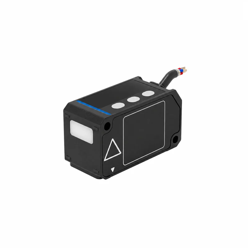
LDS-TRI
CMOS laser displacement sensors
25–1,000 mm distance requests
PCB warpage · robot positioning · packaging height
Explore configuration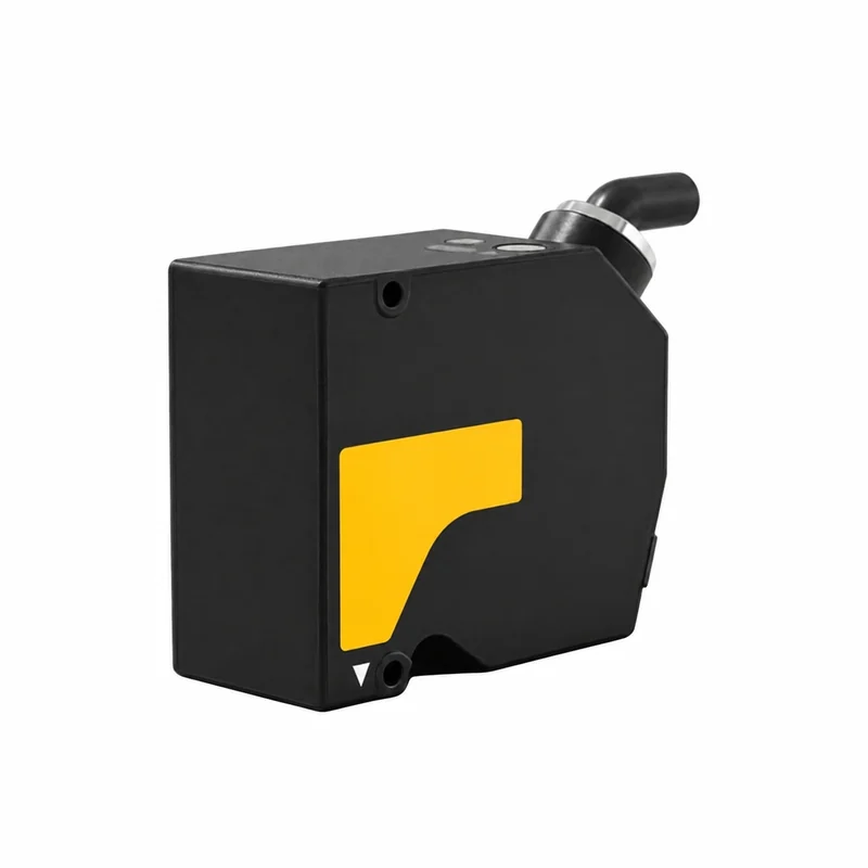
LDS-PRO
Sub-micron high-speed laser displacement gauges
10±2 to 150±40 mm requests
Electrode coating · wafer runout · spindle vibration
Explore configurationLDS-2D
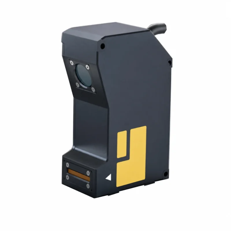
2D laser profile sensors & line scanners
Z: 10–600 mm · X: 15–500 mm requests
Gap & flushness · weld cross-section · tire profile
Explore configuration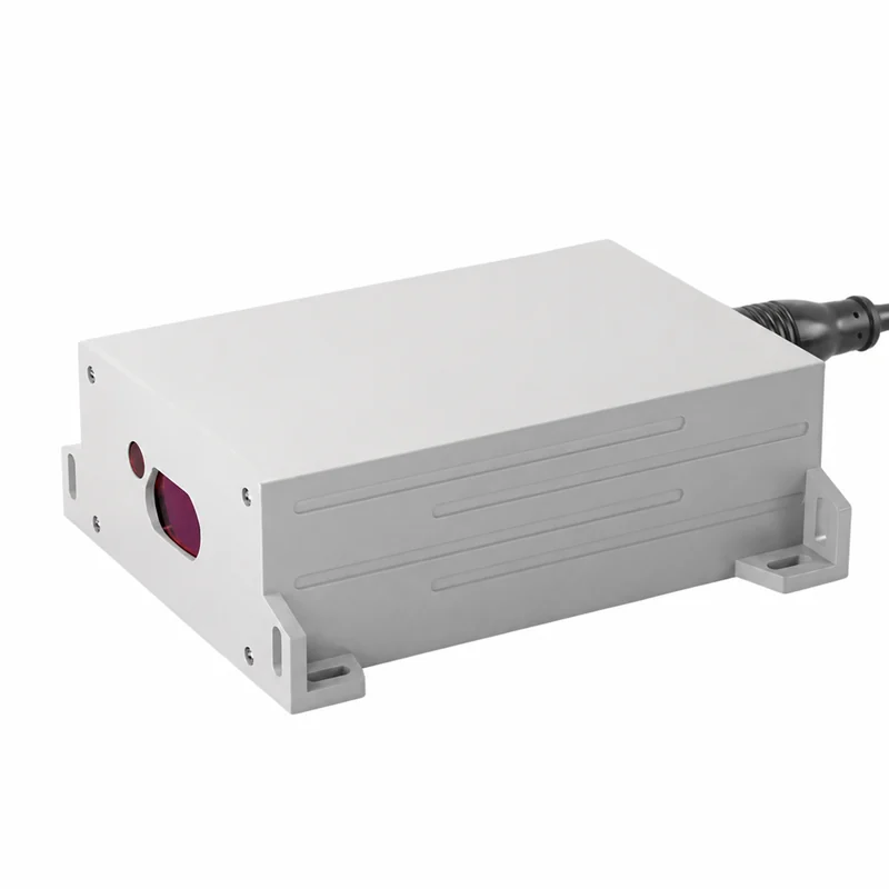
LDS-LNG
Long-range industrial laser distance sensors
0.05–50 m natural target · up to 150 m reflector requests
Stacker cranes · overhead cranes · industrial distance
Explore configuration| Measurement | Family | Primary selection decision | Explore |
|---|---|---|---|
| CMOS laser displacement sensors | LDS-TRI | 25–1,000 mm distance requests PCB warpage · robot positioning · packaging height | Review LDS-TRI ↗ |
| Sub-micron high-speed laser displacement gauges | LDS-PRO | 10±2 to 150±40 mm requests Electrode coating · wafer runout · spindle vibration | Review LDS-PRO ↗ |
| 2D laser profile sensors & line scanners | LDS-2D | Z: 10–600 mm · X: 15–500 mm requests Gap & flushness · weld cross-section · tire profile | Review LDS-2D ↗ |
| Long-range industrial laser distance sensors | LDS-LNG | 0.05–50 m natural target · up to 150 m reflector requests Stacker cranes · overhead cranes · industrial distance | Review LDS-LNG ↗ |
A SHORT ROUTE TO THE RIGHT TECHNOLOGY
Start with the task and working distance.
Review stand-off, measuring span, target finish and direct PLC outputs.
This is a starting point for selection. Surface, uncertainty, speed and integration still need review. Existing document, option, worksheet and system-scope requests stay attached for review; a model reference is kept only within its matching family. Use Send this measurement brief to carry these selector choices.
Compare the full chain
Review the head, controller, network interface and installation as one scope, including any integrated variant.
Specify the real surface
Define reflectivity, layers, finish and temperature before choosing red or blue optics.
Ask for the right evidence
Request the proposed model’s drawing, calibration conditions and integration files with your quotation.
CHOOSE THE MEASURING PRINCIPLE
Small movements. Long distances.
Different optical tools.
| Decision | Laser triangulation | Phase-shift distance |
|---|---|---|
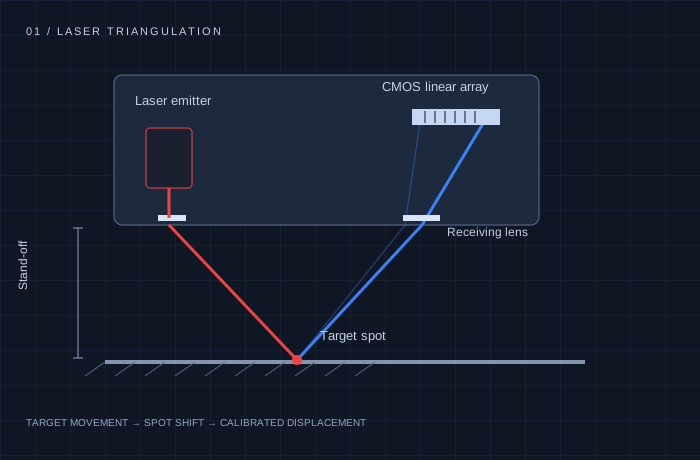
| Typical requirement | Short stand-off; micron-level displacement | Plant-scale travel; millimeter-level distance |
| How it measures | Target spot position on a CMOS detector | Phase delay of modulated returning light |
| Choose for | Thickness, runout, height, gap | Stacker cranes, long travel, remote positioning |
| Family | LDS-TRI / LDS-PRO; LDS-2D for profiles | LDS-LNG; range depends on target |
| Verify | Surface, angle, linearity, measuring rate | Reflectivity, ambient light, update rate, confidence level |
Resolution, repeatability and absolute accuracy describe different properties. Request the selected configuration’s measurement conditions.
TWO HEADS. ONE THICKNESS.
Measure the sheet,
even when it moves.
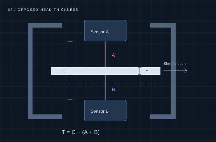
Opposed sensors measure both surfaces at the same position and time. With a calibrated fixed gap C, the geometry is:
Thickness T = C − (A + B)
Ideal rigid-body sheet motion cancels when both readings are synchronized and aligned. Real uncertainty includes both sensors, frame expansion, calibration, tilt and timing mismatch. Lateral spot offset also matters: a 0.5 mm offset with 1° sheet tilt produces about 8.7 μm of apparent thickness change. Align the spots and verify with a master thickness.
Request a matched LDS-TRI / LDS-PRO pair, synchronized calculator and C-frame. Micron-level thickness requires validation of the complete assembly.
FROM COMPONENT TO MEASUREMENT
Work from the process to the sensor.
Battery electrode & sheet thickness
Specify the complete measurement loop: two surfaces, two synchronized distance readings and one calibrated frame. Start by defining whether you need total sheet thickness or coating thickness alone.
Review the measurement plan ↗SEMICONDUCTOR / PCB / PRECISION ASSEMBLYWafer & PCB warpage
A height map becomes useful only when its reference plane, support condition and scan coordinates are defined. Treat an opaque PCB, a polished wafer and a transparent layer stack as separate optical jobs.
Review the measurement plan ↗BODY PANELS / DOOR FIT / ROBOT INSPECTIONAutomotive gap & flushness
Turn a door, hood or body-panel cross-section into two defined results: lateral separation and signed height offset. The profile, reference regions and edge rule must describe the same inspection task.
Review the measurement plan ↗ASRS / MATERIAL HANDLING / PLANT TRAVELCrane & stacker positioning
Specify a distance channel over the complete travel path, including the nearest position, moving target alignment and control-system timing. A long maximum range alone does not establish a usable positioning loop.
Review the measurement plan ↗ADDITIONAL OPTICAL METHODS / TECHNOLOGY REVIEW
Measuring interfaces or an outside diameter?
Confocal Chromatic Sensor Review
Assess single-sided surface or transparent-layer measurement using a broadband optical principle. Identify the return you need, then qualify the head, controller and material calibration together.
Review the method and access requirements ↗Laser Micrometer Diameter Review
Measure a projected diameter, width or edge with transmitted light. Define emitter/receiver access and the target envelope before selecting an optical aperture or reporting a dimensional result.
Review the method and access requirements ↗Compare the complete installation cost.
Compare two USD acquisition scopes, identify missing costs and take the worksheet to the engineering enquiry.
Open the price and scope worksheet ↗Prepare the drawings, data and acceptance scope.
Laser Sensor PLC Integration Guide
Confirm the ordered hardware, wiring drawing and data semantics together. An M12 connector or an Ethernet port describes only part of the integration.
Open the engineering checklist ↗Laser Sensor Calibration Review
Start with the quantity you need to accept, the conditions under which it is measured and the evidence that belongs to the delivered unit or complete system.
Open the engineering checklist ↗Laser Sensor Safety & Compliance
Prepare one review package for the ordered head, its optical variant and the machine around it. Start with identifiable documents and the access conditions your EHS team needs to assess.
Open the engineering checklist ↗REPLACING AN EXISTING SENSOR?
Match the whole measurement chain.
Send the exact Keyence, Micro-Epsilon, Banner, SICK or Dimetix head, controller and cable model. Review spot size, stand-off, dynamic response, pinout and PLC integration together.
Open the replacement review table ↗Your RFQ starts with five facts.
Target material. Near and far distance. Required uncertainty. Line speed. Output interface.
Request selection / CAD ↗INDUSTRIAL MEASUREMENT / RFQ
Send the requirements your machine depends on.
Define target, near/far distance, uncertainty, speed and PLC interface. Include the original model if replacing equipment.
Confirm the proposed model, drawing revision, available integration files and calibration scope. Agree an NDA before confidential transfers where required.
Confirm supply scope, price, sample/volume quantities, destination, dispatch plan and acceptance terms before ordering.
Contact [email protected]. Response and delivery timing are confirmed for the project; the form does not promise instant model approval or shipment.