
MEASURAND / OPTICAL ACCESS / SYSTEM SCOPE
Optical measurement technology selection starts with the result
Compare surface displacement, total thickness, profiles, distant position, transparent interfaces and projected dimensions before choosing a sensor family.
Screen the result, access, material and geometry together.
Use four starting answers to identify a review route. This does not select an orderable model or validate accuracy on your target.
The displayed default route is static until JavaScript initializes. Use the comparison table and direct contact links for manual review.
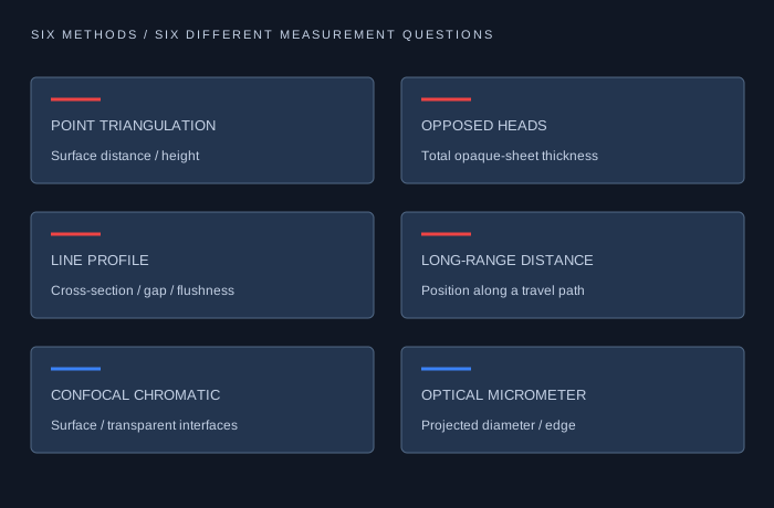
Six methods answer different dimensional questions.
| Method | Starting result | Critical review | Read more |
|---|---|---|---|
| Point triangulation | Local surface displacement / height | Stand-off, span, return path and finish | Point triangulation guide ↗ |
| Opposed-head thickness | Total opaque-sheet thickness | Both sides, aligned points, synchronized data and frame | Opposed-head thickness guide ↗ |
| Laser line profile | Cross-section / gap / flushness | X/Z field, visible edges, evaluation and motion | Laser line profile guide ↗ |
| Long-range distance | Plant-scale travel position | Near/far target return, alignment and data age | Long-range distance guide ↗ |
| Confocal chromatic | Surface / separable transparent interfaces | Broadband optics, material conversion and interface assignment | Confocal chromatic guide ↗ |
| Optical micrometer | Projected diameter / width / edge | Emitter/receiver access, aperture and edge processing | Optical micrometer guide ↗ |
Separate a surface coordinate, thickness and a projection.
A distance head reports a coordinate relative to its optical reference. Opposed heads can derive total sheet thickness from two distances and a calibrated separation. A line scanner adds a cross-section; it does not become a complete registered surface map without motion or spatial registration.
Confocal chromatic measurement can assess optically accessible interfaces with a matched broadband system. A transmitted-light micrometer evaluates edge positions or projected width across a light path. A single projection does not establish a full circumference or wall thickness.
Define uncertainty, timing and evidence after the method.
Set the required uncertainty and reference comparison, then specify usable rate, exposure/filtering, fresh data, motion registration and output semantics. Resolution and output increment are not substitutes for the uncertainty of the final dimensional result.
Compare the complete scope: optical head or paired heads, source/controller, frame or motion, cables, protective hardware, PLC/PC processing and the documents needed to commission it. Separate actual included hardware from a technology interest or requested document category.
Define calibration and acceptance evidence ↗Review the full integration path ↗HARDWARE / INSTALLATION REFERENCE
Review hardware only after choosing the measurement method.
These views cover the existing point, profile and distance families. Confocal and through-beam micrometer systems require a separate assessment.
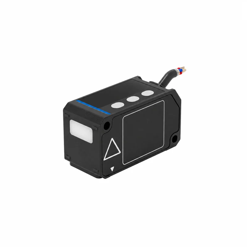
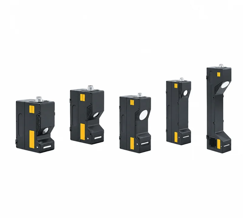
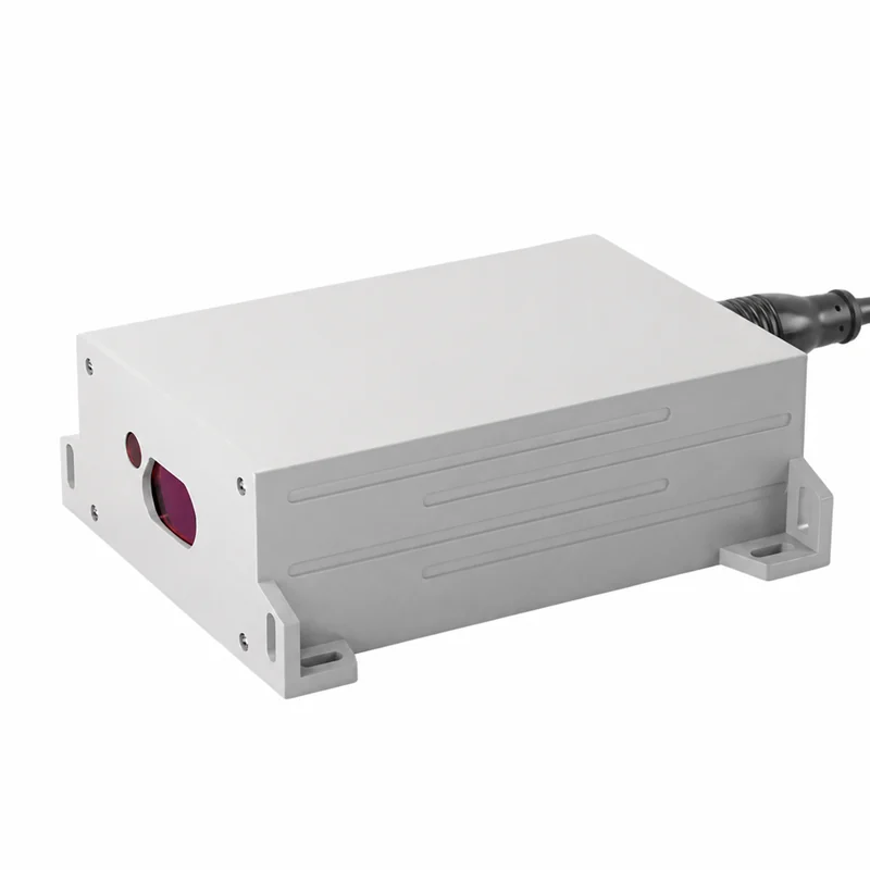
Representative housing views. Confirm the exact model, dimensions and supply scope. Housing color does not identify laser wavelength.
ADDITIONAL OPTICAL METHODS / TECHNOLOGY REVIEW
Measuring interfaces or an outside diameter?
Confocal Chromatic Sensor Review
Assess single-sided surface or transparent-layer measurement using a broadband optical principle. Identify the return you need, then qualify the head, controller and material calibration together.
Review the method and access requirements ↗Laser Micrometer Diameter Review
Measure a projected diameter, width or edge with transmitted light. Define emitter/receiver access and the target envelope before selecting an optical aperture or reporting a dimensional result.
Review the method and access requirements ↗Questions before the method is specified
Does the screening tool select an approved LDS model?
No. It routes initial requirements to a measurement-method review. Surface return, geometry, rate, uncertainty, integration and actual configuration availability still need assessment.
Can a blue laser upgrade replace confocal or through-beam optics?
No. Triangulation, broadband confocal and transmitted-light dimensional measurement use different optical arrangements. Wavelength alone does not add interface discrimination or access to a silhouette.
What happens when geometry or optical access is unknown?
The screening routes unresolved or contradictory inputs to an engineering method review. The enquiry retains the initial answers and uses a geometry-to-confirm category rather than inventing a stand-off range.
Take a defined brief to the next engineering review.
Record the required result, actual surfaces/layers, available sides, nearest/farthest position or aperture, motion, uncertainty, interface and quantity. If any are unknown, retain that uncertainty rather than substituting a guessed family specification.
Get the project-brief worksheet ↗