
INDUSTRIAL LASER MEASUREMENT / APPLICATION GUIDES
Industrial laser measurement applications, from sheet to stacker.
Industrial laser measurement starts with the result your machine needs: total sheet thickness, a registered surface map, panel gap and flushness, or distance along a travel path.
Use these guides to define the optical arrangement, installation limits, data path and acceptance test. They are engineering selection frameworks, not measured LDS customer case studies.
Send your measurement brief ↗FROM COMPONENT TO MEASUREMENT
Work from the process to the sensor.
Battery electrode & sheet thickness
Specify the complete measurement loop: two surfaces, two synchronized distance readings and one calibrated frame. Start by defining whether you need total sheet thickness or coating thickness alone.
Review the measurement plan ↗SEMICONDUCTOR / PCB / PRECISION ASSEMBLYWafer & PCB warpage
A height map becomes useful only when its reference plane, support condition and scan coordinates are defined. Treat an opaque PCB, a polished wafer and a transparent layer stack as separate optical jobs.
Review the measurement plan ↗BODY PANELS / DOOR FIT / ROBOT INSPECTIONAutomotive gap & flushness
Turn a door, hood or body-panel cross-section into two defined results: lateral separation and signed height offset. The profile, reference regions and edge rule must describe the same inspection task.
Review the measurement plan ↗ASRS / MATERIAL HANDLING / PLANT TRAVELCrane & stacker positioning
Specify a distance channel over the complete travel path, including the nearest position, moving target alignment and control-system timing. A long maximum range alone does not establish a usable positioning loop.
Review the measurement plan ↗HARDWARE / INSTALLATION REFERENCE
Different measurement tasks start with different hardware.
Point heads, line scanners and distant-position housings need different installation and data plans.
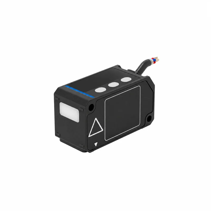
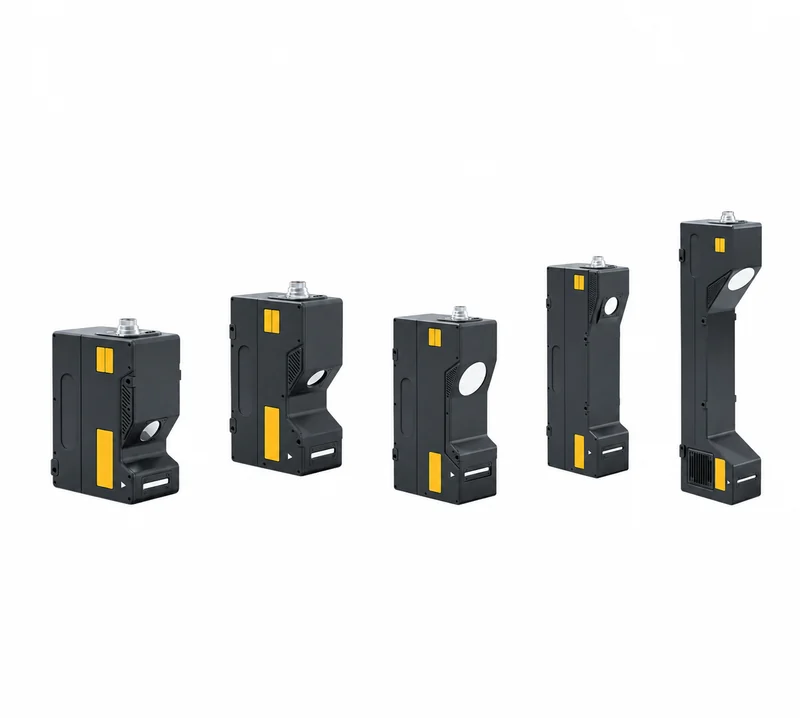
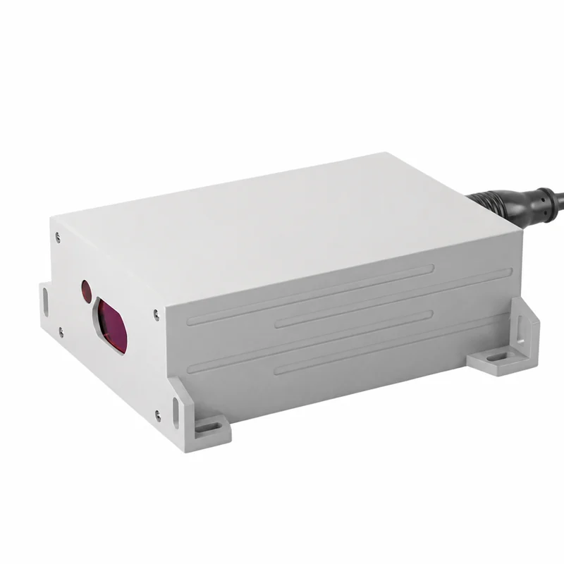
Representative housing views. Confirm the exact model, dimensions and supply scope. Housing color does not identify laser wavelength.
ADDITIONAL OPTICAL METHODS / TECHNOLOGY REVIEW
Measuring interfaces or an outside diameter?
Confocal Chromatic Sensor Review
Assess single-sided surface or transparent-layer measurement using a broadband optical principle. Identify the return you need, then qualify the head, controller and material calibration together.
Review the method and access requirements ↗Laser Micrometer Diameter Review
Measure a projected diameter, width or edge with transmitted light. Define emitter/receiver access and the target envelope before selecting an optical aperture or reporting a dimensional result.
Review the method and access requirements ↗Bring five decisions to the first review.
- Measurand: the physical quantity, datum and required uncertainty.
- Target: surface, layers, temperature and representative variation.
- Envelope: nearest/farthest position, motion and optical clearance.
- Data: acquisition timing, validity flags and the PLC or PC interface.
- Acceptance: reference method, operating conditions and agreed pass criteria.
Prepared by LDS Optical Metrology. Published and reviewed . Model specifications, document availability and the complete supply scope require confirmation in the proposed configuration.