
SURFACE / TRANSPARENT INTERFACES
Confocal chromatic displacement sensors: define the interface
Assess single-sided surface or transparent-layer measurement using a broadband optical principle. Identify the return you need, then qualify the head, controller and material calibration together.
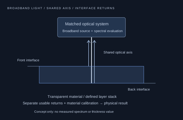
This page opens a separate optical-method review. The four existing LDS laser families do not establish an orderable confocal or micrometer configuration. Feasibility, system identity, documents and supply scope require confirmation.
Before arranging target trials, agree the representative samples, measurement and acceptance scope, handling and return arrangements, costs and schedule. A technology enquiry does not confirm a trial booking or supply commitment.
Choose the interface result before the optical head.
| Required result | Information to establish | Boundary to verify |
|---|---|---|
| Surface distance / height | Which interface, stand-off, measuring span and surface slope | Usable return and calibrated coordinate at every required position |
| Single-sided transparent thickness | Front/back interface separation, material and refractive-index/dispersion data | Resolvable interface returns and validated conversion to physical thickness |
| Several transparent layers / gaps | Complete stack, layer order, thickness limits and optical contrast | Peak assignment, minimum separation and controller capability |
| Opaque coating or metal substrate | Whether the requested result is outer height or an internal layer | Light does not reveal an interface hidden behind opaque material |
Broad-spectrum focusing is a different measurement principle.
Confocal chromatic sensing uses broadband light and optics that focus different wavelengths at different axial positions. A return associated with an in-focus interface is spectrally evaluated and mapped to a calibrated distance. It is not a red or blue triangulation head with a different software setting.
An implementation includes a matched optical head, illumination/spectral evaluation and controller, often linked by a specified optical fiber. Confirm the actual system arrangement, cable handling, mounting datum and usable optical path rather than choosing from a laser-triangulation part number.
Interface separation is not automatically physical thickness.
For transparent material, multiple interfaces can create separate returns if the optical arrangement and signal processing can resolve them. Physical thickness depends on the material behavior and calibration, including relevant refractive-index and wavelength dependence. Do not apply a universal fixed-index conversion to an unknown stack.
Provide the material names, coating/adhesive sequence, minimum and maximum layer thickness, air gaps and the exact interfaces to report. If optical data are unknown, identify that explicitly and agree a suitable reference sample or characterization step before a thickness commitment.
An opaque electrode coating, a polished wafer and a transparent glass stack are different jobs. A polished surface may need careful angular alignment; an opaque layer can hide deeper interfaces. Neither broadband illumination nor blue laser color removes those constraints.
Qualify slope, motion and the full optical path.
Review the head’s allowed stand-off, working span, receive aperture and slope behavior for the actual surface. Ask whether all required interfaces remain in the usable range through part movement and thickness extremes. Protective windows and contamination can add unwanted returns and need their own review.
Specify exposure, filtering, fresh-reading rate, output latency and how ambiguous or missing peaks are flagged. For scanned parts, include position registration and fixture/support repeatability. A repeatability value on a reference surface is not the uncertainty of your layer result.
PROPOSED QUALIFICATION / NOT A COMPLETED TEST
Agree the target trial and accepted result.
Identify the interfaces
Mark the required surface/layer result on a non-confidential cross-section and record all known/unknown material data.
Confirm the optical configuration
Review head/controller identity, stand-off/span, slope, fiber/cable routing and the document revision.
Compare representative samples
Use an agreed reference thickness/height method across stack variants, positions and process conditions.
Validate result and validity
Retain reported values, interface assignment, invalid flags and acquisition settings with the acceptance record.
These checks are a planning framework. No measured LDS performance, accredited result or interchangeable hardware is established by the guide.
Questions before the method is specified
Is a confocal chromatic sensor a laser triangulation sensor?
No. Confocal chromatic measurement uses broadband light, wavelength-dependent axial focusing and spectral evaluation. Laser triangulation uses the geometric position of a reflected spot. They need different optical and controller arrangements.
Can it measure every transparent multilayer stack from one side?
No. Interfaces must give usable, separable returns within the optical range, and the material conversion and controller processing must be suitable. Supply the stack, thickness limits and known or unknown optical properties for assessment.
Are LDS-CNF specifications or CAD released on this page?
This is a technology review entry. No LDS-CNF orderable configuration, performance envelope, stock or model-specific file is established here. The review must confirm a feasible system and its available documentation.
Bring the optical conditions to the enquiry.
Identify the required interface, layer stack, thickness limits, known or unknown optical properties, accessible side, stand-off and motion. Include required uncertainty, controller/interface needs, quantity and destination.
The review uses a geometry-to-confirm category, not a triangulation range. Earlier screening answers remain visible and removable. Start with a non-confidential brief; agree any necessary NDA and transfer method before confidential files.
RELATED METHODS / TRIANGULATION HARDWARE
Review point or profile triangulation as a separate option.
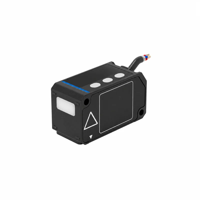
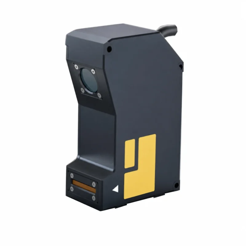
The views below show triangulation-family housing references. They depict neither a confocal probe nor a through-beam optical micrometer. Use the method guide to decide whether either approach fits your task.
Prepare the drawings, data and acceptance scope.
Laser Sensor PLC Integration Guide
Confirm the ordered hardware, wiring drawing and data semantics together. An M12 connector or an Ethernet port describes only part of the integration.
Open the engineering checklist ↗Laser Sensor Calibration Review
Start with the quantity you need to accept, the conditions under which it is measured and the evidence that belongs to the delivered unit or complete system.
Open the engineering checklist ↗Laser Sensor Safety & Compliance
Prepare one review package for the ordered head, its optical variant and the machine around it. Start with identifiable documents and the access conditions your EHS team needs to assess.
Open the engineering checklist ↗