
TRANSMITTED LIGHT / PROJECTED DIMENSION
Laser micrometer and optical diameter measurement
Measure a projected diameter, width or edge with transmitted light. Define emitter/receiver access and the target envelope before selecting an optical aperture or reporting a dimensional result.
This page opens a separate optical-method review. The four existing LDS laser families do not establish an orderable confocal or micrometer configuration. Feasibility, system identity, documents and supply scope require confirmation.
Before arranging target trials, agree the representative samples, measurement and acceptance scope, handling and return arrangements, costs and schedule. A technology enquiry does not confirm a trial booking or supply commitment.
Define the aperture, projection and edge rule.
| Required result | Information to establish | Boundary to verify |
|---|---|---|
| Diameter / projected width | Minimum/maximum dimension, target position and measurement axis | Entire silhouette stays within the calibrated aperture |
| Edge / gap position | Which edges and reference coordinate define the result | Threshold, edge direction, multiple segments and invalid detection |
| Ovality / runout assessment | Axes, rotation/translation, speed and evaluation method | A single projection is not a full roundness measurement |
| Transparent fiber / glass / film | Material, geometry and required edge discrimination | Transmission/refraction may require a suitable algorithm and actual sample trials |
Two-sided optical access is part of the measurement.
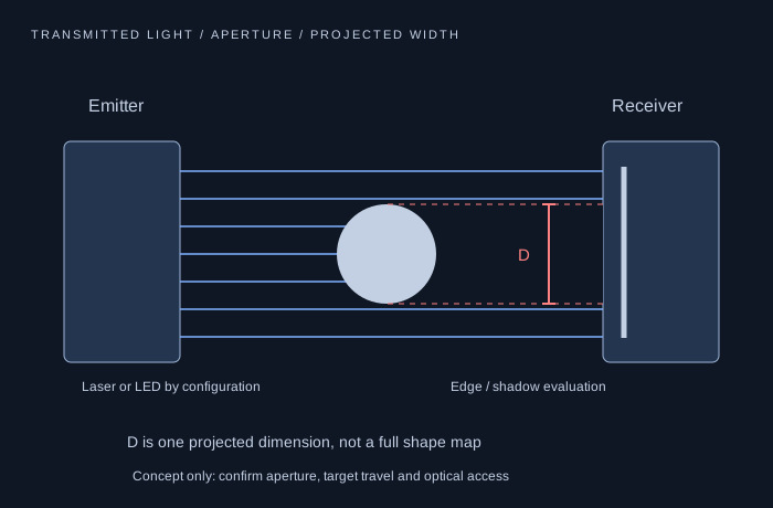
An optical micrometer evaluates how a target changes the transmitted light reaching a receiver. Depending on the system, edge positions or a calibrated shadow width provide the dimensional result. This measures a projection across the light path rather than the distance from one head to a reflecting surface.
Provide the emitter-to-receiver gap, available mounting space and the full lateral target excursion. The measurement aperture, target diameter and component separation are different dimensions. Include the target and its motion margin inside the usable calibrated field; do not size an aperture from diameter alone.
Laser and LED systems need their own edge assessment.
The market uses both laser and optical-micrometer terminology. Some systems use a laser source; others use LED illumination and imaging. Confirm the source, optical arrangement and ordered hardware. A method name does not establish a particular emitter wavelength or laser classification.
Opaque metal, textured extrusion and transparent fiber can give different edge signals. Transparent targets can refract and redistribute light instead of making a simple dark silhouette. Agree an appropriate edge rule, threshold behavior and valid-target detection on representative samples.
Dust, droplets, vibration and misalignment can alter the apparent edge. Specify cleaning/protection and review target tilt, orientation and any nearby features that could be mistaken for the measured segment.
Define the projection, motion and accepted shape result.
One measurement axis yields a projected width or diameter under a defined pose. It does not prove roundness, a full circumference or wall thickness. Ovality and runout require a stated axis/rotation plan and an evaluation method; a changing center position is not automatically a changing diameter.
Specify line speed, rotation, exposure and fresh sample rate together. Include any averaging window and synchronization with part position. Capture the smallest required spatial feature with adequate sampling and test the complete data path, including invalid flags and latency.
Compare results with an agreed dimensional reference under the same definition and conditions. Include reload/position variation, representative finishes and expected motion. Define what evidence is needed before a system or process is accepted.
PROPOSED QUALIFICATION / NOT A COMPLETED TEST
Agree the target trial and accepted result.
Define the measured dimension
State projected diameter/width, selected edge, gap, axis and any ovality/runout calculation.
Close the installation envelope
Record target extremes and motion, aperture, emitter/receiver gap, mounting and cable/protection space.
Trial edges and movement
Include all relevant materials/finishes, transparent variants, positions, speeds and deliberate missing-target cases.
Confirm output and comparison
Agree units, reference method, uncertainty, quality flags, data age and the accepted processing settings.
These checks are a planning framework. No measured LDS performance, accredited result or interchangeable hardware is established by the guide.
Questions before the method is specified
Does optical micrometer always mean a laser source?
No. Optical dimensional systems can use laser or LED illumination, depending on the implementation. Confirm the proposed source, optics and safety documentation for the actual configuration.
Can a single projected diameter establish roundness or wall thickness?
No. A single projection describes one dimension at one pose. Full shape, ovality/runout or wall thickness needs the appropriate additional axes, motion or measurement principle and a defined evaluation method.
Is an LDS-MIC model or accuracy guaranteed by this guide?
No. This page initiates an optical micrometer assessment. A feasible head/controller arrangement, aperture, usable target behavior, performance and documentation must be confirmed separately.
Bring the optical conditions to the enquiry.
Identify the projected dimension, minimum/maximum target, aperture and target movement, emitter/receiver access, finish and speed. Include required uncertainty, controller/interface needs, quantity and destination.
The review uses a geometry-to-confirm category, not a triangulation range. Earlier screening answers remain visible and removable. Start with a non-confidential brief; agree any necessary NDA and transfer method before confidential files.
RELATED METHODS / TRIANGULATION HARDWARE
Review point or profile triangulation as a separate option.
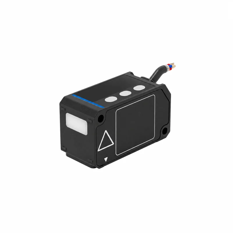
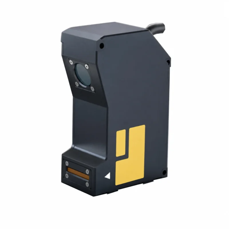
The views below show triangulation-family housing references. They depict neither a confocal probe nor a through-beam optical micrometer. Use the method guide to decide whether either approach fits your task.
Prepare the drawings, data and acceptance scope.
Laser Sensor PLC Integration Guide
Confirm the ordered hardware, wiring drawing and data semantics together. An M12 connector or an Ethernet port describes only part of the integration.
Open the engineering checklist ↗Laser Sensor Calibration Review
Start with the quantity you need to accept, the conditions under which it is measured and the evidence that belongs to the delivered unit or complete system.
Open the engineering checklist ↗Laser Sensor Safety & Compliance
Prepare one review package for the ordered head, its optical variant and the machine around it. Start with identifiable documents and the access conditions your EHS team needs to assess.
Open the engineering checklist ↗