
ENGINEERING DOCUMENTATION / REVIEW GUIDE
Laser sensor PLC integration: match the full data path
Confirm the ordered hardware, wiring drawing and data semantics together. An M12 connector or an Ethernet port describes only part of the integration.
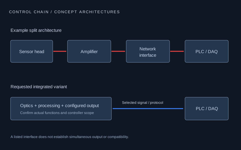
Choose the evidence for the interface you will actually use.
| Interface path | Request before connection | Verify in commissioning |
|---|---|---|
| 4–20 mA / voltage | Output variant, supply/headroom, permitted load, endpoints and fault behavior | Units, sign, clipping, settling and invalid-signal interpretation |
| RS485 Modbus RTU | Serial settings and the exact function/address/data map | Data type, scale, multi-register order, status and freshness |
| IO-Link | Matching device identity, IODD revision and master/port requirements | Process-data layout, parameters, diagnostics and replacement behavior |
| Industrial Ethernet / SDK | Exact protocol/firmware; matching device file or SDK documentation | Payload, cycle/latency, sequence/timestamps and loss handling |
Check the connector drawing from the correct side.
Compare the full head, cable and controller order codes. Record M12 coding, pin count, male/female connector and whether the pin diagram is a mating-face or wiring-side view. A matching shell and pin count do not establish matching pin functions.
Review supply, ground, analog reference, switching polarity, trigger and shield termination against both device and PLC documentation. Cable color is an identification aid, not a substitute for the model-specific drawing. Keep the approved wiring revision with the machine record.
Define analog scaling and headroom without guessing a pinout.
Identify which physical distance corresponds to each output endpoint, whether the output direction is inverted and what the ordered variant does for invalid targets or out-of-range readings. Confirm the receiving channel mode and usable load before applying a conversion.
For a current loop, supply voltage must cover the transmitter’s required minimum voltage, the current-dependent drop across the total load and other circuit drops. The relevant current and voltage limits come from the selected hardware. A generic fixed load-resistance formula cannot replace those limits.
Validate the full loop at known positions, including invalid return, restart and recovery. A plausible PLC number does not prove correct scaling or a fresh optical acquisition.
Decode registers and process data with explicit validity.
The Modbus Organization describes operations on 16-bit data words. That does not assign a distance register, signed format or engineering scale to an LDS configuration. Request the exact function, address convention, width, units, scale and multi-register ordering, with example frames from the proposed device documentation.
For IO-Link, match device identity and revision to the IODD and master setup. For other ordered networks, confirm the matching ESI, GSDML or EDS file where applicable. A generic Ethernet connection does not establish one of those protocol implementations.
The ordered interface may be provided by the head, a separate controller or a protocol gateway. Include every required module, power connection, mounting envelope and transfer stage in the supply scope and end-to-end timing check.
For a 2D scanner, distinguish raw calibrated profiles from processed scalar results. Agree which device computes the result, the PLC payload/cycle budget and the destination for raw data. Record quality flags, sequence or timestamps and the response to stale or missing measurements.
PROPOSED REVIEW / NOT A COMPLETED TEST
Make the checks part of the agreed project scope.
Freeze the identities
Record ordered hardware, firmware, cable, controller and every document revision before testing.
Verify known states
Use agreed physical positions and target conditions to check units, direction, scaling and validity.
Measure the complete timing path
Separate new acquisition from repeated output; include processing, network transfer and PLC scan.
Exercise the diagnostic path
Verify invalid/stale values, restart and communication loss against the machine control plan.
The proposed checks do not establish a released LDS model, completed calibration, accreditation or certified machine-safety function.
Questions before you request the files
Can I connect by M12 pin count or wire color?
No. Confirm coding, connector view and the exact pin functions for the complete device and cable order codes. The mating connector shape does not establish electrical compatibility.
Does RS485 identify the distance register map?
No. RS485 describes the electrical communication layer. You still need the protocol settings and model-specific function, address, type, scale, ordering and validity definitions.
Does an Ethernet port mean the sensor supports every PLC protocol?
No. Confirm the ordered protocol, firmware and matching device file or SDK. Raw profile transport and processed PLC results may use different paths.
Request evidence for your actual configuration.
Send the full device and controller model, measuring requirement, document revisions already held, quantity and destination. Ask to agree an NDA and transfer method before sharing confidential drawings.
Download or read the project worksheet ↗HARDWARE / INSTALLATION REFERENCE
Check connector coding, mating direction and acquisition hardware.
Connector appearance is useful for layout. The actual pinout, protocol and device file must match the ordered variant.
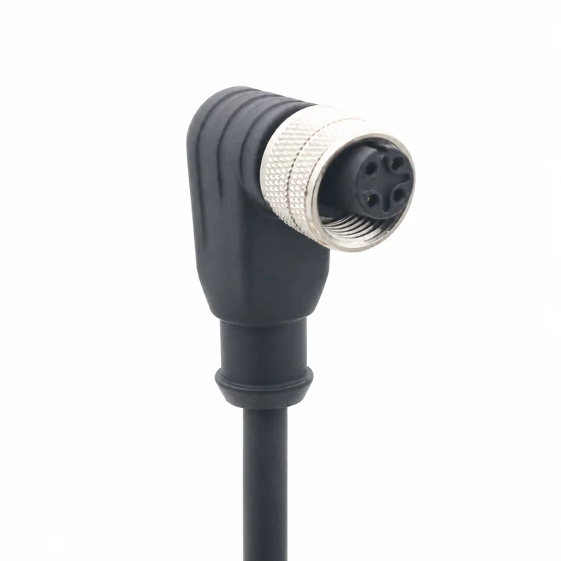
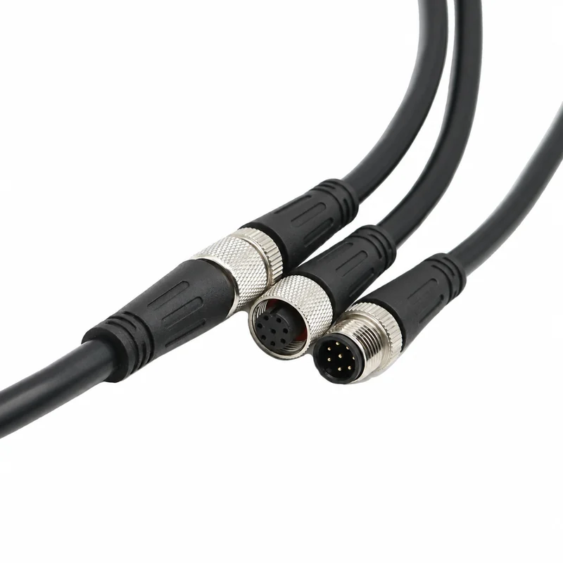
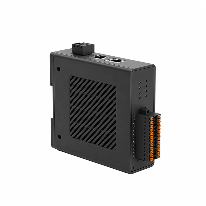
Representative housing views. Confirm the exact model, dimensions and supply scope. Housing color does not identify laser wavelength.