
03 / A COMPLETE CROSS-SECTION
2D laser profile sensors & line scanners
Measure the shape. Understand the profile.
Use a laser profile sensor to evaluate gap and flushness, weld geometry, tire tread and pin coplanarity. Select field of view, profile rate and processing around the feature you need to resolve.
Configure LDS-2D ↗Request the proposed model’s CAD package ↗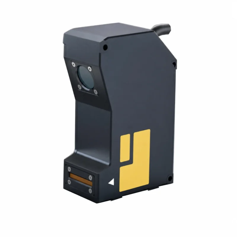
LASER CLASS / INDUSTRIAL ENVIRONMENT
Confirm the class and test scope of the ordered variant.
Laser label and installation
Request the actual label, classification basis and instructions for this LDS-2D configuration. Include reflective targets, external optics, covers and setup/service access in the machine review.
Environmental and market records
Match declared ingress/temperature limits and EMC, shock or vibration evidence to the complete assembly and test conditions. Identify the destination and applicable declaration/report scope.
Class, ratings, certificates and document availability require configuration-specific confirmation. A measurement output is not a certified personnel-protection function.
LINE PROFILES / PROCESSED RESULTS
Plan the data path as carefully as the field of view.
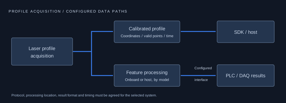
Raw profile / SDK
Confirm calibrated coordinate units, point validity, timestamps, packet format, SDK platform and licensing. GigE Vision and a proprietary Ethernet SDK are different integration choices.
Processed feature / PLC
Define the datum, region of interest and result: step height, gap, flushness, width, weld angle or cross-section. Confirm where computation runs and the PLC’s supported data structure and cycle.
Motion / 3D reconstruction
A profile is a cross-section. Along-travel spacing depends on line speed divided by profile rate. Use the appropriate encoder or timing reference and include dropped-profile handling.
| Application | Define before selecting | Acceptance result |
|---|---|---|
| Gap & flushness | Two surfaces, edge fit, datum and permissible occlusion | Gap / height difference with valid-point status |
| Weld profile | Coordinate frame, seam region, angle and section baseline | Specified geometric results at production speed |
| Connector pins / cooling plates | Smallest feature, lateral spacing, reflectivity and reference plane | Coplanarity / step results with coverage criteria |
Request the allowed field, point-count, exposure and processing combinations. Maximum headline figures need not be available simultaneously.
Compare the complete installation cost.
Compare two USD acquisition scopes, identify missing costs and take the worksheet to the engineering enquiry.
Open the price and scope worksheet ↗SELECTION REVIEW / LDS-2D
Set the acceptance conditions with the configuration.
Z: 10–600 mm · X: 15–500 mm requests
Up to 2,048 points per profile requested
500–4,000 Hz requests · GigE Vision / SDK review
These are selection envelopes. Maximum field, rate, resolution and interface functions require confirmation for the same ordered configuration.
Specify X width at the near and far Z limits. Field of view changes with distance; do not assume the maximum X and Z ranges belong to one scanner.
Profile frequency, exposure and point count interact. Define the smallest feature, line speed and required valid-point coverage on the actual surface.
Confirm whether the ordered system supplies calibrated profiles, onboard width/height results or SDK processing. GigE Vision compatibility is separate from a generic Ethernet TCP/IP connection.
Application focus: Gap & flushness · weld cross-section · tire profile
Existing-family references: Keyence LJ-V7000 / LJ-X8000 · Micro-Epsilon scanCONTROL · Cognex DSMax. Send the full suffix, drawing and integration requirements for assessment.
HARDWARE / INSTALLATION REFERENCE
A profile scanner needs a clear line and receiving field.
Housing shape and connector access are part of the installation. Confirm the calibrated field of view on the model drawing.
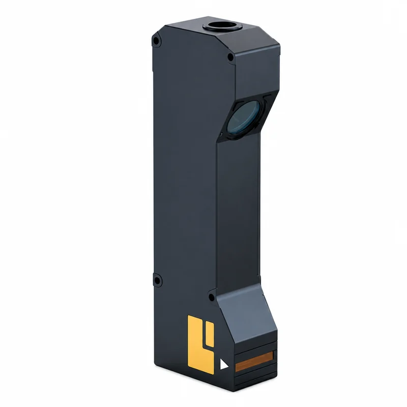
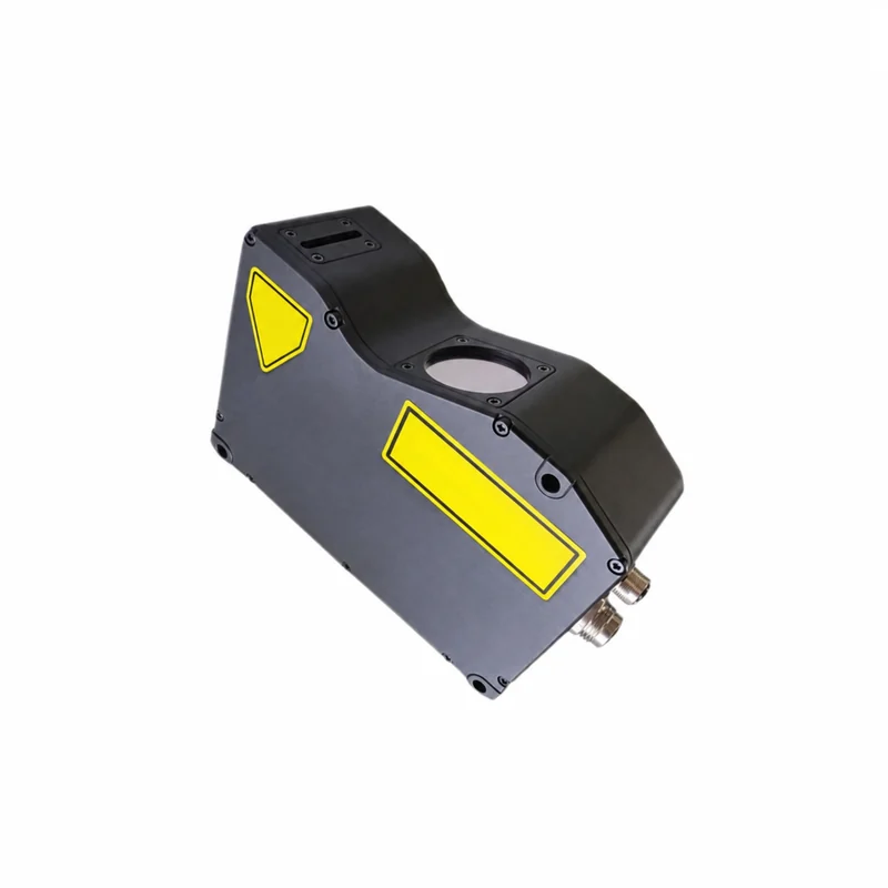
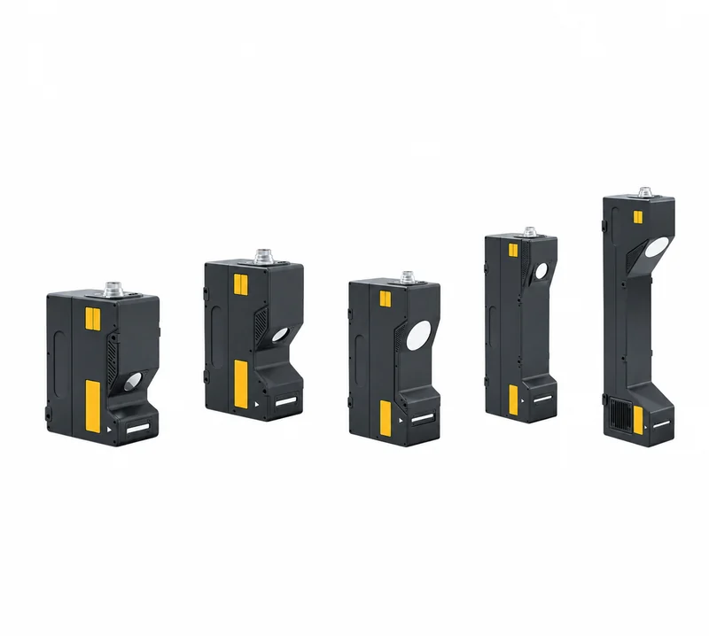
Representative housing views. Confirm the exact model, dimensions and supply scope. Housing color does not identify laser wavelength.
LDS-2D / MEASURING GEOMETRY
Keep the optical path clear across the measuring field.
Use the measurement concept to define the target position and available access. Request the selected head’s calibrated field and clearance drawing.
Review the working principle ↗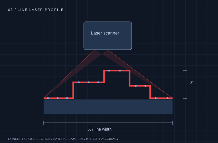
CHOOSE THE MEASURING PRINCIPLE
Small movements. Long distances.
Different optical tools.
| Decision | Laser triangulation | Phase-shift distance |
|---|---|---|
| Typical requirement | Short stand-off; micron-level displacement | Plant-scale travel; millimeter-level distance |
| How it measures | Target spot position on a CMOS detector | Phase delay of modulated returning light |
| Choose for | Thickness, runout, height, gap | Stacker cranes, long travel, remote positioning |
| Family | LDS-TRI / LDS-PRO; LDS-2D for profiles | LDS-LNG; range depends on target |
| Verify | Surface, angle, linearity, measuring rate | Reflectivity, ambient light, update rate, confidence level |
Resolution, repeatability and absolute accuracy describe different properties. Request the selected configuration’s measurement conditions.
LDS-2D / ENGINEERING HANDOFF
Request the files your design review needs.
Ask for the proposed model’s current revision. File availability, supported functions and calibration scope are confirmed during configuration review.
Dimensioned drawing / 3D STEP
Add this document request ↗REQUEST / clearanceOptical clearance & mounting drawing
Add this document request ↗REQUEST / pinoutModel-specific M12 pin assignment
Add this document request ↗REQUEST / modbusAnalog scaling / RS485 register map
Add this document request ↗REQUEST / networkFieldbus description file / SDK
Add this document request ↗REQUEST / calibrationCalibration scope & report sample
Add this document request ↗REQUEST / safetyLaser safety & environmental documentation
Add this document request ↗M12 pin count is only the first check.
Housing dimensions, optical-axis height, mounting holes, connector clearance and cable bend space.
Connector coding, supply and ground, analog reference, output polarity, load and shield termination. Request the drawing for both complete part numbers.
Scaling, register or process-data map, units, invalid-data flags, trigger behavior, update period and the correct IODD / ESI / GSDML / EDS file where supported.
FROM COMPONENT TO MEASUREMENT
Plan the application around the measurement.
Wafer & PCB warpage
A height map becomes useful only when its reference plane, support condition and scan coordinates are defined. Treat an opaque PCB, a polished wafer and a transparent layer stack as separate optical jobs.
Review the measurement plan ↗BODY PANELS / DOOR FIT / ROBOT INSPECTIONAutomotive gap & flushness
Turn a door, hood or body-panel cross-section into two defined results: lateral separation and signed height offset. The profile, reference regions and edge rule must describe the same inspection task.
Review the measurement plan ↗LDS-2D / BEFORE THE DRAWING REVIEW
Resolve the questions that change the configuration.
Does a 2D scanner produce a complete 3D surface by itself?
A profile is one cross-section. Reconstructing a moving surface requires the appropriate motion or encoder reference, synchronization and processing.
Can maximum field, point count and scan frequency be combined?
Not without a model-specific operating envelope. Exposure, selected region, target return and processing load can constrain the usable combination.
Is GigE Vision the same as an industrial PLC protocol?
No. Confirm the image/profile transport, SDK format and any processed-result fieldbus separately, together with PLC cycle time and data size.
LDS-2D / CONFIGURATION & DOCUMENT REQUEST