
01 / INTEGRATED POINT MEASUREMENT
CMOS laser displacement sensors
Bring displacement measurement directly into your machine.
Specify an all-in-one CMOS laser triangulation sensor for robotic positioning, PCB warpage and height measurement. Review built-in control and direct PLC outputs for your installation.
Configure LDS-TRI ↗Request the proposed model’s CAD package ↗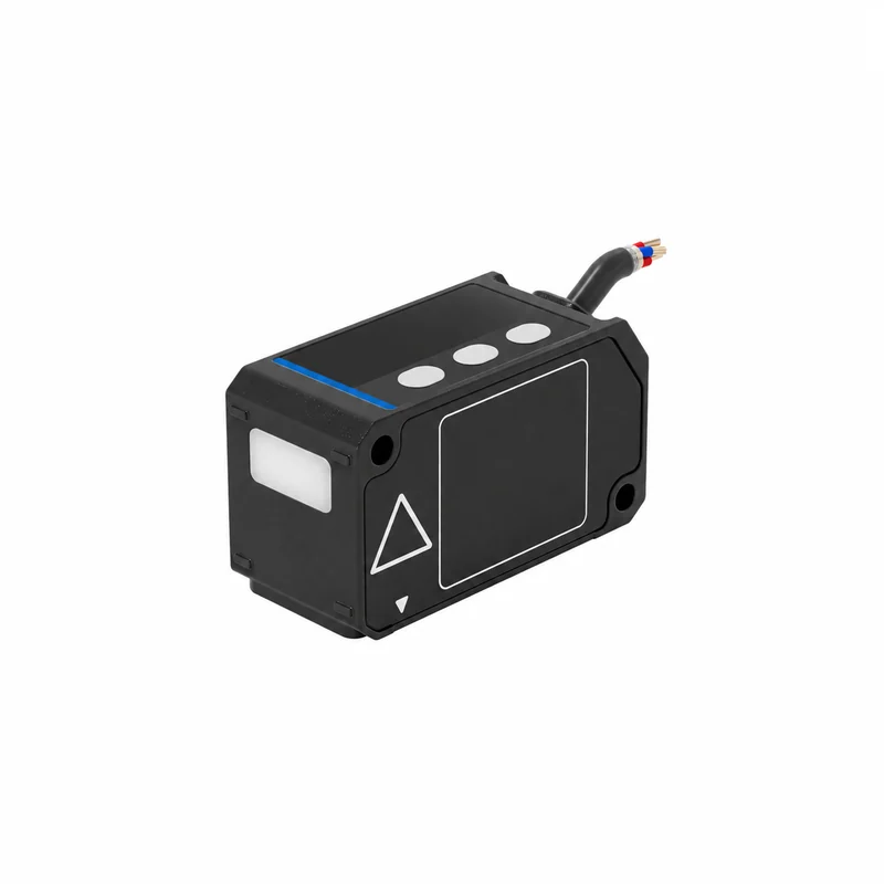
LDS-TRI / INQUIRY CONFIGURATIONS
Choose the stand-off before the output variant.
Use these references to describe the requested geometry. They are planning identifiers, not released model specifications. The quotation must confirm the order code, achievable performance, optical arrangement and drawing.
| Inquiry reference | Center / half-span request | Requested near → far | Qualification needed | Enquire |
|---|---|---|---|---|
| LDS-TRI-025 | 25 ± 5 mm | 20 → 30 mm (10 mm span) | Repeatability, linearity, spot and output variant require confirmation. | Use LDS-TRI-025 ↗ |
| LDS-TRI-030 | 30 ± 10 mm | 20 → 40 mm (20 mm span) | Repeatability, linearity, spot and output variant require confirmation. | Use LDS-TRI-030 ↗ |
| LDS-TRI-050 | 50 ± 20 mm | 30 → 70 mm (40 mm span) | Repeatability, linearity, spot and output variant require confirmation. | Use LDS-TRI-050 ↗ |
| LDS-TRI-100 | 100 ± 40 mm | 60 → 140 mm (80 mm span) | Repeatability, linearity, spot and output variant require confirmation. | Use LDS-TRI-100 ↗ |
| LDS-TRI-200 | 200 ± 100 mm | 100 → 300 mm (200 mm span) | Repeatability, linearity, spot and output variant require confirmation. | Use LDS-TRI-200 ↗ |
| LDS-TRI-400 | 400 ± 200 mm | 200 → 600 mm (400 mm span) | Repeatability, linearity, spot and output variant require confirmation. | Use LDS-TRI-400 ↗ |
| LDS-TRI-1000 | Up to 1,000 mm distance request | Specify both limits | Working-distance request up to 1,000 mm. Specify the near and far positions; no symmetric span is assigned. | Use LDS-TRI-1000 ↗ |
Near/far values above are geometry arithmetic, not measured performance. Confirm linearity, repeatability, temperature drift, spot size, measuring rate, supply voltage, enclosure rating and exact connector for the selected configuration.
LASER CLASS / INDUSTRIAL ENVIRONMENT
Confirm the class and test scope of the ordered variant.
Laser label and installation
Request the actual label, classification basis and instructions for this LDS-TRI configuration. Include reflective targets, external optics, covers and setup/service access in the machine review.
Environmental and market records
Match declared ingress/temperature limits and EMC, shock or vibration evidence to the complete assembly and test conditions. Identify the destination and applicable declaration/report scope.
Class, ratings, certificates and document availability require configuration-specific confirmation. A measurement output is not a certified personnel-protection function.
INTEGRATED CONTROL / PLC OUTPUTS
Count the complete sensing chain.
A separate head, amplifier and communication module can be appropriate for a multi-channel system. For a compact machine, an integrated variant may reduce cabinet space and wiring points. Compare the complete supply scope before comparing unit prices.
Specify the required 4–20 mA, 0–10 V, RS485 Modbus or IO-Link variant. Confirm simultaneous-output behavior rather than assuming all listed signals are active together.
The Keyence IL model catalogue distinguishes sensor heads from amplifier units. It does not establish a fixed price difference or universal alternative.
Read the original IL model catalogue ↗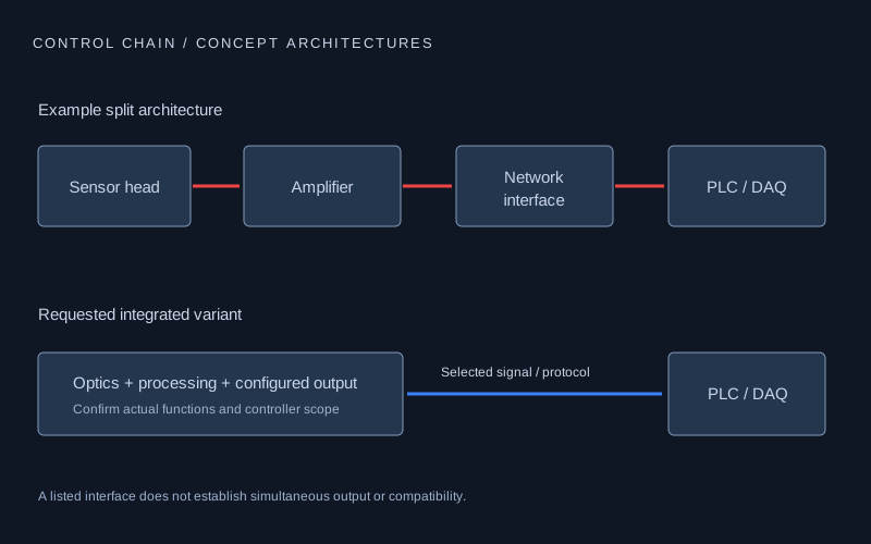
Compare the complete installation cost.
Compare two USD acquisition scopes, identify missing costs and take the worksheet to the engineering enquiry.
Open the price and scope worksheet ↗SELECTION REVIEW / LDS-TRI
Set the acceptance conditions with the configuration.
25–1,000 mm distance requests
Repeatability qualified per configuration
4–20 mA · 0–10 V · RS485 · IO-Link
These are selection envelopes. Maximum field, rate, resolution and interface functions require confirmation for the same ordered configuration.
Center / half-range requests: 25±5, 30±10, 50±20, 100±40, 200±100 and 400±200 mm. Specify the nearest and farthest working positions; stand-off distance is not the measurement span.
Ask for OLED setup, a built-in controller and the required analog or digital variant. Confirm whether outputs operate simultaneously, as well as NPN/PNP configuration and cable pinout.
Black rubber, polished steel and abrupt reflectivity changes need target trials at the intended exposure and speed. Record invalid readings and drift as well as averaged repeatability.
Application focus: PCB warpage · robot positioning · packaging height
Existing-family references: Keyence IL-030 / IL-065 / IL-100 / IL-300 · Micro-Epsilon optoNCDT 1320 / 1420 · SICK OD Value · Banner Q4X. Send the full suffix, drawing and integration requirements for assessment.
HARDWARE / INSTALLATION REFERENCE
Compare the display, optical window and mounting envelope.
Bring the space around the head into the configuration review, including access to controls and cable bend clearance.
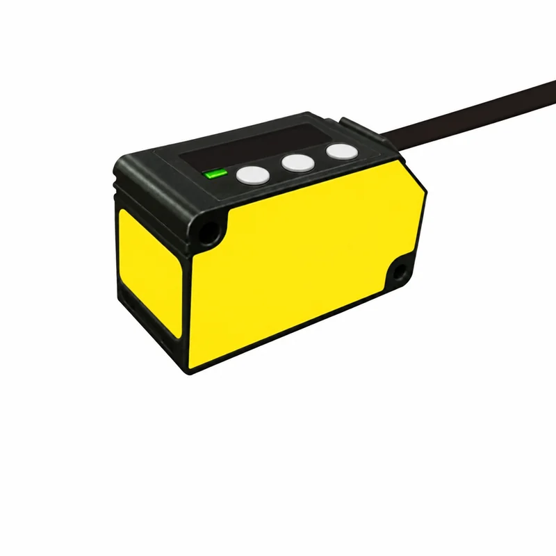
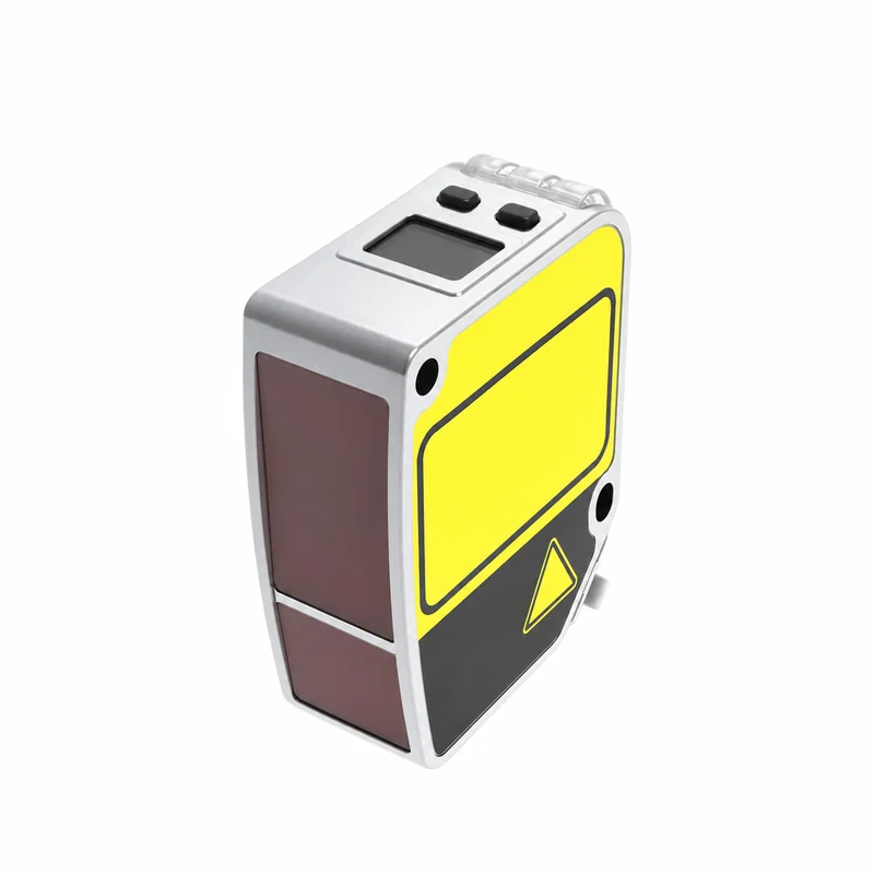
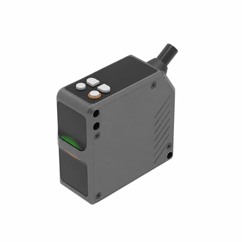
Representative housing views. Confirm the exact model, dimensions and supply scope. Housing color does not identify laser wavelength.
LDS-TRI / MEASURING GEOMETRY
Keep the optical path clear across the measuring field.
Use the measurement concept to define the target position and available access. Request the selected head’s calibrated field and clearance drawing.
Review the working principle ↗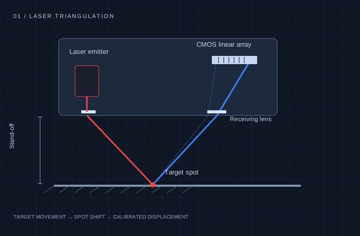
TWO HEADS. ONE THICKNESS.
Measure the sheet,
even when it moves.
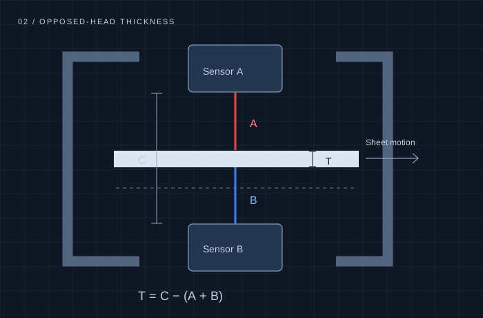
Opposed sensors measure both surfaces at the same position and time. With a calibrated fixed gap C, the geometry is:
Thickness T = C − (A + B)
Ideal rigid-body sheet motion cancels when both readings are synchronized and aligned. Real uncertainty includes both sensors, frame expansion, calibration, tilt and timing mismatch. Lateral spot offset also matters: a 0.5 mm offset with 1° sheet tilt produces about 8.7 μm of apparent thickness change. Align the spots and verify with a master thickness.
Request a matched LDS-TRI / LDS-PRO pair, synchronized calculator and C-frame. Micron-level thickness requires validation of the complete assembly.
CHOOSE THE MEASURING PRINCIPLE
Small movements. Long distances.
Different optical tools.
| Decision | Laser triangulation | Phase-shift distance |
|---|---|---|
| Typical requirement | Short stand-off; micron-level displacement | Plant-scale travel; millimeter-level distance |
| How it measures | Target spot position on a CMOS detector | Phase delay of modulated returning light |
| Choose for | Thickness, runout, height, gap | Stacker cranes, long travel, remote positioning |
| Family | LDS-TRI / LDS-PRO; LDS-2D for profiles | LDS-LNG; range depends on target |
| Verify | Surface, angle, linearity, measuring rate | Reflectivity, ambient light, update rate, confidence level |
Resolution, repeatability and absolute accuracy describe different properties. Request the selected configuration’s measurement conditions.
LDS-TRI / ENGINEERING HANDOFF
Request the files your design review needs.
Ask for the proposed model’s current revision. File availability, supported functions and calibration scope are confirmed during configuration review.
Dimensioned drawing / 3D STEP
Add this document request ↗REQUEST / clearanceOptical clearance & mounting drawing
Add this document request ↗REQUEST / pinoutModel-specific M12 pin assignment
Add this document request ↗REQUEST / modbusAnalog scaling / RS485 register map
Add this document request ↗REQUEST / networkFieldbus description file / SDK
Add this document request ↗REQUEST / calibrationCalibration scope & report sample
Add this document request ↗REQUEST / safetyLaser safety & environmental documentation
Add this document request ↗M12 pin count is only the first check.
Housing dimensions, optical-axis height, mounting holes, connector clearance and cable bend space.
Connector coding, supply and ground, analog reference, output polarity, load and shield termination. Request the drawing for both complete part numbers.
Scaling, register or process-data map, units, invalid-data flags, trigger behavior, update period and the correct IODD / ESI / GSDML / EDS file where supported.
FROM COMPONENT TO MEASUREMENT
Plan the application around the measurement.
Battery electrode & sheet thickness
Specify the complete measurement loop: two surfaces, two synchronized distance readings and one calibrated frame. Start by defining whether you need total sheet thickness or coating thickness alone.
Review the measurement plan ↗SEMICONDUCTOR / PCB / PRECISION ASSEMBLYWafer & PCB warpage
A height map becomes useful only when its reference plane, support condition and scan coordinates are defined. Treat an opaque PCB, a polished wafer and a transparent layer stack as separate optical jobs.
Review the measurement plan ↗LDS-TRI / BEFORE THE DRAWING REVIEW
Resolve the questions that change the configuration.
Is the center distance the same as the measuring range?
No. A 100±40 mm request describes an 80 mm measuring span from 60 to 140 mm. These geometry values define an inquiry; the selected model’s datasheet establishes its actual ratings.
Can analog, RS485 and IO-Link all operate together?
Do not assume every listed interface operates simultaneously. Confirm the exact output variant, wiring, switching mode and communication behavior in the written configuration.
Can I replace an IL or Q4X without rewiring?
Send the complete original part number and wiring drawing. Connector pin count, mounting dimensions and similar nominal range do not establish electrical or optical interchangeability.
LDS-TRI / CONFIGURATION & DOCUMENT REQUEST